Intel
®
Server Board S5500BC User’s Guide 3
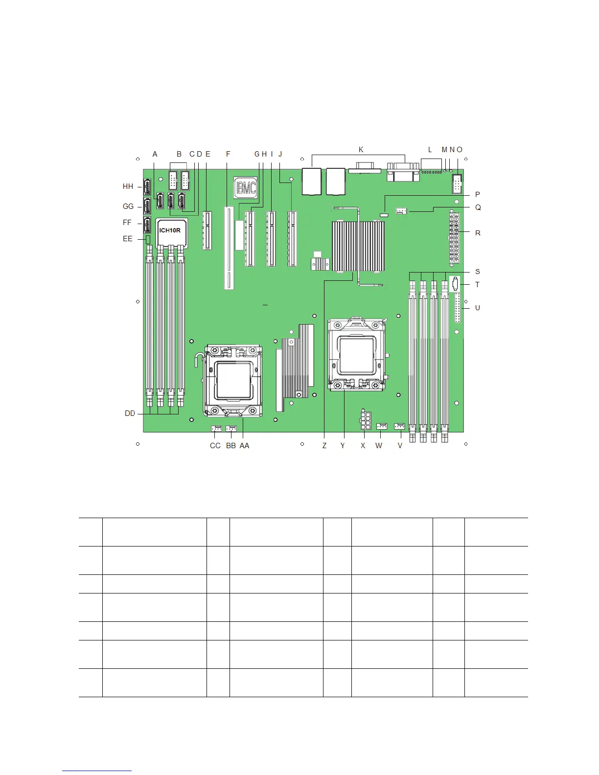
Connector and Component Locations
Figure 2. Server Board Connector and Component Locations
A. SATA 3 L. Diagnostic LEDs W. CPU 1 fan
header
HH. SATA 2
B. Internal dual port
USB2.0 header
M. Status LED X. CPU Power
Connector
C. SATA 5 N. ID LED Y. CPU Socket 1
D. SATA 4 O. External Serial B
header
Z. Intel
®
IOH 5500
chipset
E. Slot 3, PCI Express* x4 P. SATA Key AA. CPU Socket 2
F. Slot 4, 32-bit/33 MHz
PCI
Q. System fan 3 header BB. BB CPU 2 Fan
header
G. Intel
®
RMM3 slot R. Main power
connector
CC. System Fan 1
header