23
Operation
Operation
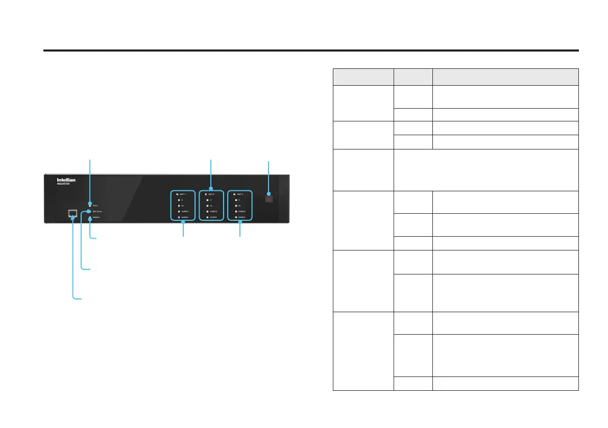
The following table shows status indicators on the face of
each mediator module.
Intelligent Mediator Front Panel
The following gure shows the mediator’s front panel.
Management Port
for PC/Web M&C
Power
on/off button
M&C Server
status indicator
Antenna 1
C/Ku/Ka(MEO)/
Ka(GEO)-band
Antenna 2
C/Ku/Ka(MEO)/
Ka(GEO)-band
Antenna 3
C/Ku/Ka(MEO)/
Ka(GEO)-band
Mediator status
indicator
Power indicator
LED Display Color Description
Power
Steady
Green
The mediator is powered on.
Off The mediator is powered off.
M&C Server
Green The M&C Server is connected.
Off The M&C Server is not connected.
Mediator (In
Single Data
Center(SDC)
System)
This function is not supported in SDC System.
Mediator (In
Dual Data
Center(DDC)
System)
Steady
Green
Data Center is connected as Primary.
Steady
Yellow
Data Center is connected as
Secondary.
Off Data Center is not connected.
Antenna
1(ANT1)
Antenna
2(ANT2)
Antenna
3(ANT3)
Steady
White
Antenna modules are communicating.
Off
Antenna modules are not
communicating.
C-band
Ku-band
Ka-band(GEO)
Ka-band(MEO)
Steady
Green
The Hot Standby state is primary, and
Tx/Rx services are active.
Steady
Yellow
The Hot Standby state is secondary
or backup, and Rx service is active
only. The module is ready to assume
Primary Role if needed.
Off All services are not active.
 Loading...