P/N 146278999-2 (ML) • REV G • ISS 08MAR19 3 of 26
8
EN: Installation Sheet
Introduction
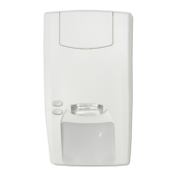
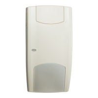
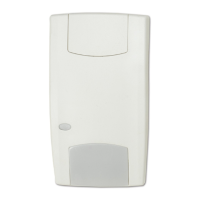
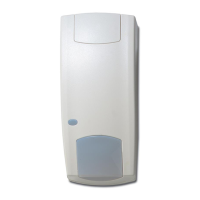
The VE1016 series consists of models VE1016 and
VE1016AM. These detectors use PIR or PIR-AM sensors.
They have a patented mirror, pyro, and signal processing
technology.
Installation guidelines
The technology used in these detectors resists false alarm
hazards. However, avoid potential causes of instability such as
(see Figure 1):
• Direct sunlight on the detector
• Strong draughts onto the detector
• Heat sources within the detector field of view
• Large animals within the detector field of view
• Obscuring the detector field of view with large objects,
such as furniture
• Objects within 50 cm (20 in.) of the anti-masking (AM)
detector
• Installing two detectors facing each other and less than
50 cm (20 in.) apart
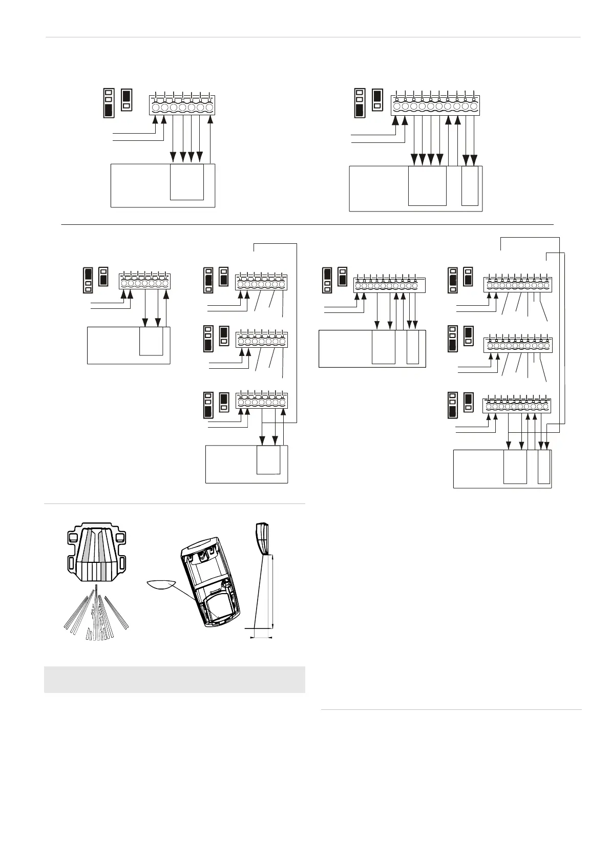
Installing the detector
Figure 7
Standard connection (factory default)
VE1016
VE1016 VE1016AM
Zone X
1
2
3
4
5
6
7
GND
+12V
Alarm
Alarm
Tamper
WT
Tamper
J3
J4
CP
Zone Y
+12V
Tamper
WT
Tamper
1
2
3
4
5
6
7
8
9
10
GND
Alarm
D/N-Rtest
AM
AM
Alarm
Zone X
CP
Zone Y
+12V
Tamper
WT
Tamper
1
2
3
4
5
6
7
8
9
10
GND
Alarm
AM
AM
Alarm
Zone X
Zone Y
+12V
Tamper
WT
Tamper
GND
Alarm
AM
AM
Alarm
Zone X
+12V
Tamper
WT
Tamper
GND
Alarm
D/N-Rtest
AM
AM
Alarm
1
2
3
4
5
6
7
8
9
10
1
2
3
4
5
6
7
8
9
10
1
2
3
4
5
6
7
8
9
10
CP
CP
Zone X
1
2
3
4
5
6
7
GND
+12V
Alarm
Alarm
Tamper
WT
Tamper
Zone X
GND
+12V
Alarm
Alarm
Tamper
WT
Tamper
GND
+12V
Alarm
Alarm
Tamper
WT
Tamper
GND
+12V
Alarm
Alarm
Tamper
WT
Tamper
1
2
3
4
5
6
7
1
2
3
4
5
6
7
1
2
3
4
5
6
7
CP
J3
J4
J3
J4
J3
J4
J3
J4
J3
J4
D/N-Rtest
J3
J4
J3
J4
J3
J4
J3
J4
VE1016AM
CP
(1)
(2)
Normal
larmA
Tamper
Short
AM/TF
4.7 k
9.4
0
Ω
kΩ
Ω
8
Normal
larmA
Tamper
Short
4.7 k
9.4
0
Ω
kΩ
Ω
8
Normal
larmA
Tamper
Short
4.7 k
9.4
0
Ω
kΩ
Ω
8
+12V
Tamper
WT
Tamper
GND
Alarm
AM
AM
Alarm
D/N-Rtest
8
Normal
larmA
Tamper
Short
AM/TF
4.7 k
9.4
0
Ω
kΩ
Ω
88
D/N-Rtest
9 1
8 2
7 3
6 45
1 2 3 5 7 8 9
4
D
4
C
4
B
4
A
6
A
6
B
6
C
6
D
240 cm
(7 ft. 10 in.)
90 cm
(2 ft. 11 in.)
(1) (2)