26 Mini-Wave PE4 Installation Guide
Copyright © 2006 Intermatic, Inc.
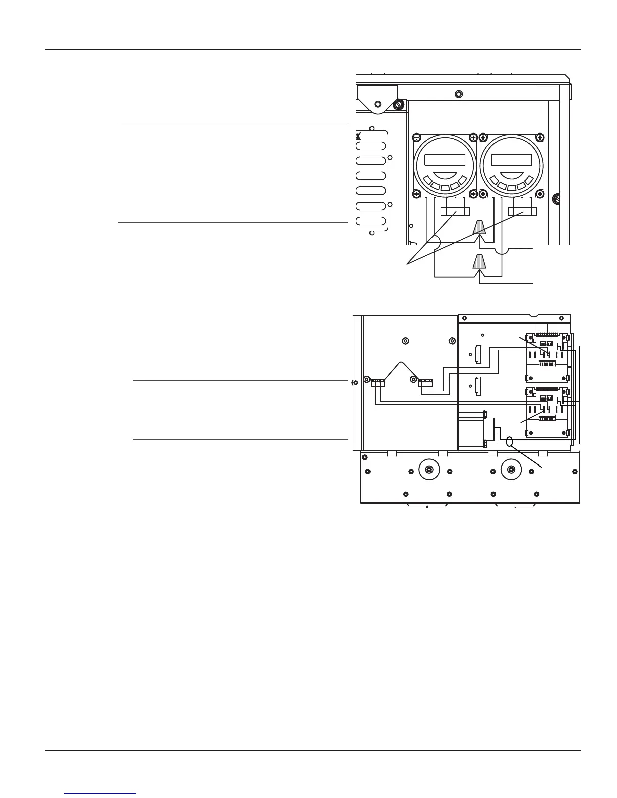
Connect to wires from Terminals 3 and 5 of
the newly installed timer and route the wires
into the Chassis Wire Access Hole.
NOTE: Depending on your installation, continue
to “Installing a Second Timed Function”
(immediately below) or jump to “Installing a
Fireman’s Switch” (following). You cannot have
both the Second Timed Function and the Cool-
Down Period in the Mini-Wave Control Center
at the same time.
Installing a Second Timed
Function
Crimp two 1/4” female spade terminals onto
both wires.
Route wires from the Chassis Wire Access
Hole, behind the chassis and connect the
terminals to either of the two 1/4” male spade
terminals labeled Ext. Timer located on the
lower Control Board.
NOTE: This connection is a dry contact
connection. Any voltage supplied to these
two connectors will damage the control
board and void the warranty.
Reassemble the chassis and low-voltage
divider into the panel.
Reinstall the Deadfront onto the Control
Panel.
Depending on the version of the Control Board,
the second timer will now control:
Relay #5 if you have Control Board Version #1
Relay #4 if you have Control Board Version #2
9.
1.
3.
4.
•
•
Pump Timer
New Timer
Chassis
Wire Access
Hole
120Vac
Supply
1 2 3 5 1 2 3 5
Pump Timer
New Timer
Chassis
Wire Access
Hole
120Vac
Supply
1 2 3 5 1 2 3 5
Figure 5-8Figure 5-8
Back of
Control Chassis
24VAC
Trans
Ext.
Timer
New
Ext.
Timer
Pump
Chassis Wire
Access Hole
24VAC
Back of
Control Chassis
24VAC
Trans
Ext.
Timer
New
Ext.
Timer
Pump
Chassis Wire
Access Hole
24VAC
Figure 5-9Figure 5-9