Five: Installing System Options 27
Providing a brighter solution.™
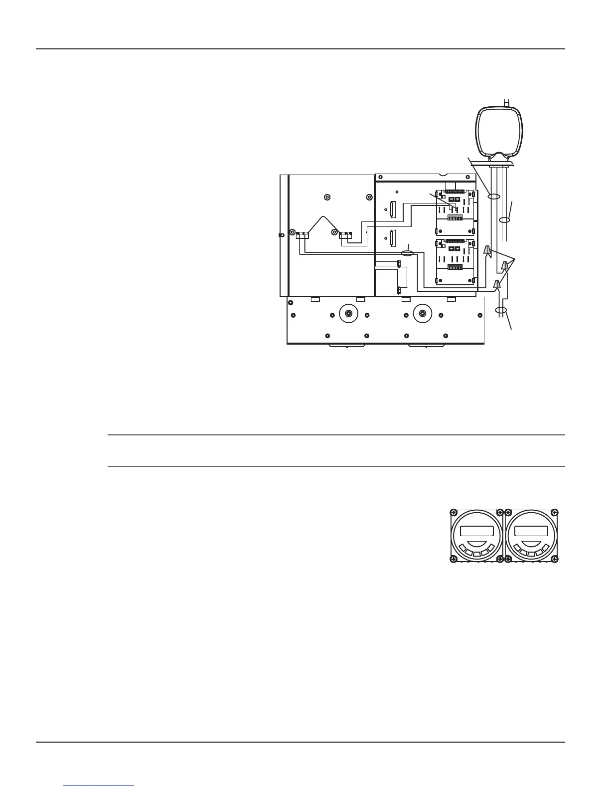
Installing a Fireman’s Switch
Route wires from the Chassis
Wire Access Hole behind the
chassis and out to the low
volrtage Raceway.
Reinstall the Chassis in the
enclosure.
Connect one of the wires from
the New Timer to either of the
Fireman’s Switch wires from the
heater.
Connect the remaining Brown
wire from the New Timer to
either of the Brown Fireman’s
Switch wires from the PE650
Receiver.
Connect the remaining Brown
wire from the PE650 Receiver to
the remaining Fireman’s Switch
wire from the heater.
Refer below to Fireman’s Switch
Programming Instructions to program the Fireman’s Switch Timer.
Programming the Fireman’s Switch
NOTE: Please reference the heater owner’s manual for for your heat exchanger’s recommended
cool-down time settings for the Fireman’s Switch.
Program your desired ON and OFF times on your Pump Timer for
your lter pump.
Program the same ON time as your Pump Timer for the Fireman’s
Switch Timer.
EXAMPLE: Assuming the heater owner’s manual recommends a ve-
minute cool-down time for the heat exchanger:
Program an OFF time on the Fireman’s Switch Timer that is ve
minutes less than the OFF time programmed on the Pump Timer.
This will ensure that the heater is OFF for at least ve minutes
before the pump shuts down, allowing proper cool down.
1.
2.
3.
4.
5.
6.
1.
2.
3.
Back of
Control Chassis
24VAC
Trans
Ext.
Timer
Pump
Chassis Wire
Access Hole
New
Timer
Pump
Timer
Wires From
New Timer
Make connection
with connectors
provided
Fireman’s Switch
Wires From Heater
Water Temp
Wires
(Black/White)
Fireman Switch
Wires
(Brown/Brown)
Back of
PE650
Receiver
Back of
Control Chassis
24VAC
Trans
Ext.
Timer
Pump
Chassis Wire
Access Hole
New
Timer
Pump
Timer
Wires From
New Timer
Make connection
with connectors
provided
Fireman’s Switch
Wires From Heater
Water Temp
Wires
(Black/White)
Fireman Switch
Wires
(Brown/Brown)
Back of
PE650
Receiver
Back view of both the Chassis and PE650 ReceiverBack view of both the Chassis and PE650 Receiver
Figure 5-10Figure 5-10
Pump
Timer
Fireman
Switch
Timer
Example:
On Time 9:00 AM On Time 9:00 AM
Off Time 1:00 PM Off Time 12:55 PM
Pump
Timer
Fireman
Switch
Timer
Example:
On Time 9:00 AM On Time 9:00 AM
Off Time 1:00 PM Off Time 12:55 PM
Figure 5-11Figure 5-11