INTERTEK TESTING SERVICES
Test Report Number: HK08060834-1 Page 14 of 72
FCC ID: T7HCT8015
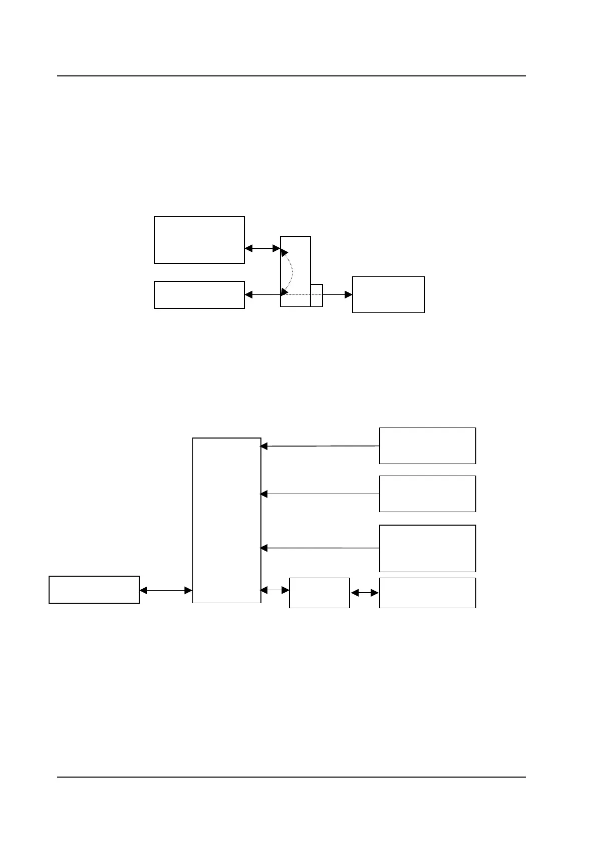
3.2 Conducted Emission Test Configuration
The setup and equipment setting were made in accordance with ANSI C63.17. The
antenna of EUT transmitter was replaced by a coaxial cable. The impendence matching
of connection, cable loss and external RF attenuator were taken into account. The EUT
was arranged to communicate via a fixed carrier frequency between its transmitter and a
companion device. The transmission was configured in burst mode with pseudo-random
data as typical as normal operation.
Figure 3.2.1
3.3 Conducted Monitoring and Operational Test Configuration
Figure 3.3.1
3.4 EUT Exercising Software
The EUT exercise program (if any) used during radiated and conducted testing was
designed to exercise the various system components in a manner similar to a typical use.
EUT
Spectrum
Analyzer
Companion
Device
Directional
Coupler
EUT
Multiport
Combiner
Companion
Device
Pulse Signal
Generator
SMIQ Vector
Signal Generator
3-channel
Interference
Generator
20 dB
attenuato