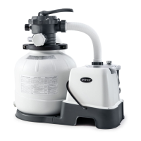
The sand filter removes suspended particles but does not sanitize your pool. Pool chemistry
is
a specialized area and you should consult your local pool service specialist for details.
Model:
ECO20110-2
ECO15110-2
Power:
110
-1
20VoltAC
110-120VoltAC
Amperaqe: 4.5 A
2.5 A
Ideal Salt Level:
3000 ppm (parts per million)
3000 ppm
Maximum Sanitizer Output/hour:
11
qrams/hour
7 qrams/hour
E.C.O. Cell Output Current:
800mA
500mA
Maximum workinq pressure:
2 bar (30 psi)
2 bar (30 psi)
Effective filtering area:
0. 13 m
2
(
1 .44
ft2)
0.1
m
2
(1.07
ft2)
Maximum Flow Rate:
8140 LPH (2150 GPH)
6055 LPH (1600 GPH)
Recommended filtering
No.
20
si
lica
sand
55
Kg
(
121
Lbs)
No.
20
sil
i
ca
sand
35
Kg
(77
Lbs)
media quantity:
or olass
sand
38
Kg
(84
Lbs).
or
glass
sand
25
Ko
(55
Lbs).
Recommended filtering
No. 20 silica sand or glass sand. Particle size range 0.45
to
0.85
media (Not included):
mm
(0.018 to 0.033 inches). Uniformity Coefficient less than 1.75.
Limited Warranty:
see "Limited Warranty"
TOOLS REQUIRED: One (1) Phillips screwdriver
Pump location and mounting:
• The system must be installed on a solid level and vibration-free base.
• Provide a location protected from the weather, moisture, flooding and freezing
temperature.
• Provide adequate access, space and lighting for routine maintenance.
• Pump motor requires free circulation
of
air for cooling.
Do
not install the pump in a
damp
or
non-ventilated location.
A team
of
2
or
more people is recommended for setting up this product.
Motor pre-filtering assembly setup:
1. Remove the sand filter and its accessories from the packaging carefully and inspect for
any visible damage.
For
missing
or
damaged parts contact the appropriate lntex Service
Center listed in the separate "Authorized service Centers" sheet.
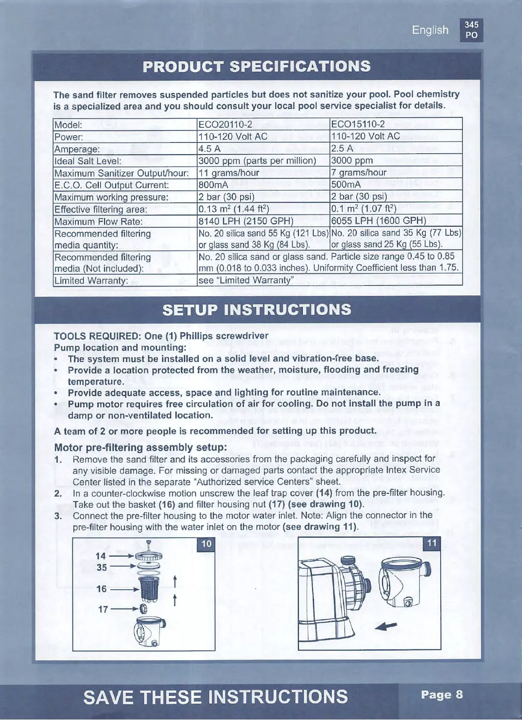
2. In a counter-clockwise motion unscrew the l
eaf
trap cover (14) from
the
pre-filter housing.
Take out the basket
(16) and filter housing nut (17) (see drawing 10).
3. Connect the pre-filter housing to the motor water inlet. Note: Align the connector in the
pre-filter housing with the water inlet on the motor
(see drawing 11).
'f
14--+-
~
35---+
~
16-----
1
17----+0
~
t
t