299
A
S AVE THESE INSTRUCTIONS
(299IO) SPA (JET + BUBBLE) ENGLISH 7.5” X 10.3” PANTONE 295U 08/20/2018
English
Page 11
SET UP (continued)
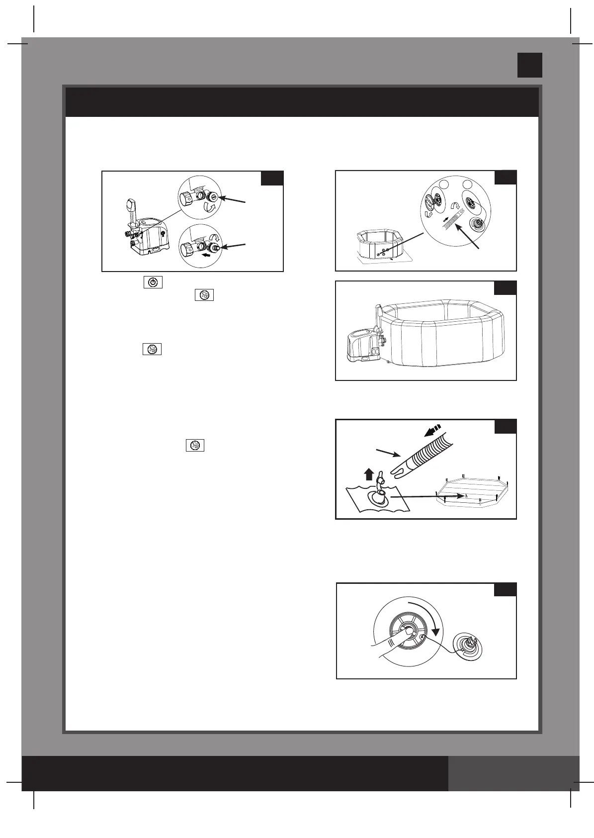
Inate the Spa Cover Air Bladder
1.
Opentheinationvalveandinserttheinationhose
(7)
intothevalve;presstoinateuntilitisrmtothe
touch but not hard
(see drawing 6)
.
2.
Disconnecttheinationhose
(7)
from the air blower
inationoutletandthevalve.
3.
Replacethecontrolbaseinationcap
(9)
back; close and
recesstheinationvalve.
NOTE:
If there is a need to add some air to the spa tub wall or
spacoverairbladderaftertheyhavebeensetup,refertoabove“InatetheSpaTubWall”and“Inatethe
Spa Cover Air Bladder” sections. The cover air bladder is preinstalled inside the spa cover. If it needs to be
reinstalled,placetheuninatedairbladderinsidethespacoverlipbeforeinatingthebladder.
4.
Press the button to turn on the control unit panel
buttonsrst.Pressthebuttontoinatethespatub
wallfor8to10minutesuntilitisrmtothetouchbutnot
hard
(see drawing 5)
.
IMPORTANT:
Donotoverinateorusehighpressureair
compressortoinate.
5.
Press the button again to turn it off.
6.
Replace the air valve cap back.
NOTE:
The cap is designed to be screwed on and off.
Never exert force as this could cause the complete
internalinationsystemofthevalvetocomeloose.See“SpaTubAirValveFastening”forvalve
maintenance.
6
7
5
Deation
For Spa Tub Wall:
1.
Unscrew the cap to reveal the stem, push the stem in
and turn 90 degree right to secure it in the down position
(see drawing 7)
.
2.
Oncethedeationiscompleted,pushthesteminand
turn90degreelefttoreturnittotheinationposition.
3.
Replace the cap back.
NOTE:
Todeatethespatubforstorage,see“STORAGE”
section.
For Cover Air Bladder:
1.
Pullvalvecapoutandsqueezethevalveatitsbaseuntildeated.
2.
Close and recess the valve back.
7
4
7
1 2
3
9
24
2.
Unscrewthecontrolbaseinationcap
(9)
torevealtheairblowerinationoutlet,insertoneendofthe
inationhose
(7)
into the outlet and turn to the right to lock it
(see drawing 3)
.
3.
Unscrewtheairvalvecaptorevealthestemintheuppositionforination.Inserttheotherendofthe
inationhose
(7)
into the valve and turn to the right to lock it in position
(see drawing 4)
.
 Loading...