SECTION 11—OPTIONS
Part No. 1163197 45 Insignia
™
Installing/Removing the IV/O2 Holder
CAUTION
The IV/O2 holder can only be installed on the left side due to the angle of the plate between the
step tube and the IV/O2 holder frame. Installation of the IV/O2 holder on the right side cannot be
achieved due to interference of the IV/O2 holder with the back upholstery.
NOTE:Rightandleftaredeterminedbythesittinginthewheelchair.
Installing
NOTE:Forthisprocedure,refertoFI GURE 11.4andFIGURE 1 1.5 onpage46.
1. Removetheleftanti‐tipper.RefertoInstalling/AdjustingAnti‐tippers
on page 37oftheowne r’smanual,p/n1163197.
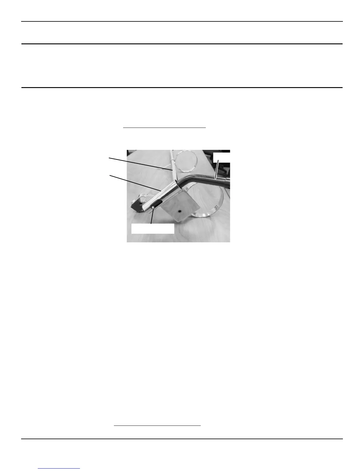
2. Inserttheanti‐tipperintotheIV/O2holdermountingtubeuntilthereleasebuttonisvisiblethroughtheopeninginthebottom
oftheIV/O2holdermountingtube(FIGURE 11.4).
FIGURE 11.4 Installing Anti-Tipper into IV/O2 Holder Mounting Tube
NOTE:WhenperformingSTEP3,theIV/O2holdermountingtubewillslideovertopofthesteptubewhiletheanti‐tipperwillslide
insidethesteptube.
3. SlidetheIV/O2holderandanti‐tipperassemblyontothesteptubeand,whilepressingthereleasebutton,insertthe
anti‐tipperinto
thesteptube(Detail“A ” and“D”inFIGURE 11.5).
4. Ensurethereleasebuttonlocksintheholeonthebottomofthesteptube(Detail“A ” and“D”inFIGURE 11.5).
NOTE:MountingbracketofIV/O2holdershouldbepositionedbetweenthetwoaxlemountingpositionsonverticalframetube.
5. Securemountingbracket
andsupportblockagainstverticalframetubewithmountingscrew(Detail“A ” and“B”in
FIGURE 11.5).Tightensecurely.
6. Removethetopmountingscrewthatsecuresthebackupholsterytothebackcane(Detail“A ” inFIGURE 11.5).
7. SecuretheuppermountingbracketoftheIV/O2holderandbackupholsterytotheback
canewiththemountingscrew
removedinSTEP6.Tightensecurely(Detail“C”inFIGURE 11.5).
Removing
NOTE:Forthisprocedure,refertoFIGURE 11.5.
1. Pressthereleasebuttoninandremovetheanti‐tipper(Detail“D”).
2. Removethemountingscrewthatsecuresthemountingbracketandsupportblockagainstverticalframetube(Detail
“A ” and“B”).
3. RemovethetopmountingscrewthatsecurestheIV/O2holderandbackupholstery
tothebackcane(Detail“C”).
4. RemovethemountingtubeoftheIV/O2holderoffofthesteptube(Detail“A”).
5. Installtheanti‐tipper.RefertoInstalling/AdjustingAnti‐tippers
onpage 37oftheowner’smanual,p/n 1163197.
6. Securethebackupholstery tothebackcanewiththemountingscrewremovedinSTEP2(Detail“C”).
IV/O2 Holder
Mounting Tube
Release Button
IV/O2 Holder
Anti-Tipper
BOTTOM VIEW OF IV/O2
HOLDER WITH ANTI-TIPPER
INSTALLED
 Loading...