35
Matrix Mono
Part 2 - Engineering Data
Matrix Mono
34
Matrix Mono Engineering Data Book
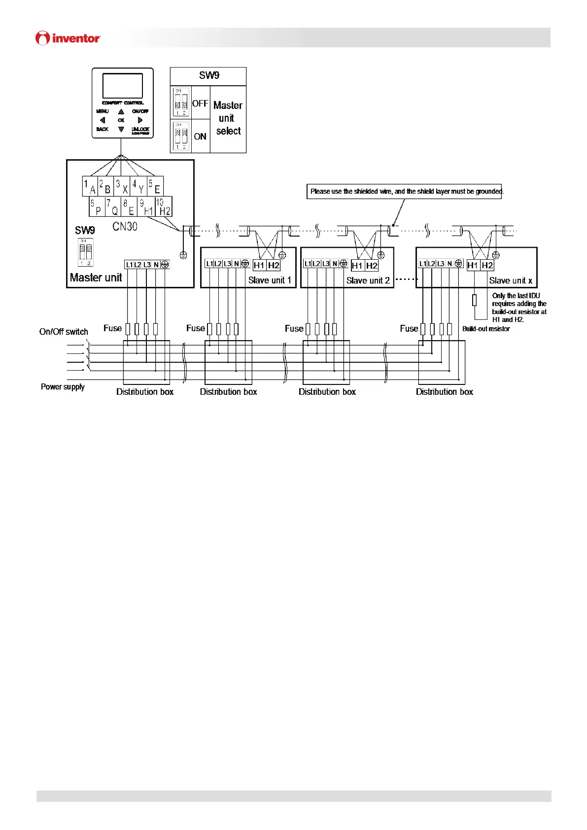
Combinaon system diagram
Figure 2-4.4 Combinaon system diagram for single phase 4~16kW models
Matrix Mono
35
Part 2 - Engineering Data
Figure 2-4.5 Combinaon system diagram for three phase 12~16kW models
Notes:
1. Inventor recommends 6 units to be controlled by one controller and installed by reversed return water system for
beer hydraulic equilibrium.
2. In order to ensure the success of automac addressing, all machines must be connected to the same power supply and
powered on uniformly.
3. Only the master unit can connect the controller, and SW9 on hydronic PCB should be switched to “on” for the master
unit. The slave units can not connect the controller.
4. Please use the shielded wire and the shield layer must be grounded.
5. When the communicaon between the units is unstable, please add a network matching wire between the ports H1
and H2 at the terminal of the communicaon system
6.When connecng to the power supply terminal, use the circular wiring terminal with the insulaon casing (see Figure
2-4.6).
7.Use power cord that conforms to the specificaons and connect the power cord firmly. To prevent the cord from being
pulled out by ext
ernal force, make sure it is fixed securely.
8. If circular wiring terminal with the insulaon casing cannot be used, please make sure that: Do not connect two power
cords with different diameters to the same power supply terminal (may cause overheang of wires due to loose wiring)
(See Figure 2-4.7).
Figure 2-4.6 Figure 2-4.7
 Loading...