75
Matrix Mono
Part 3 - Installaon and Field Sengs
Matrix Mono
74
Inventor Matrix Mono Engineering Data Book
Table 3-4.1: Wiring requirements
Item Description AC/DC Required number of conductors Maximum running current
1 Solar energy kit signal cable AC 2 200mA
2 User interface cable AC 5 200mA
3 Room thermostat cable AC 2 or 3 200mA(a)
4 Boiler control cable / 2 200mA
5 Thermistor cable for T1B DC 2 (b)
9 DHW pump control cable AC 2 200mA(a)
10 3-way valve control cable AC 2 200mA(a)
11 3-way valve control cable AC 2 or 3 200mAC
12 Thermistor cable DC 2 (b)
13 Booster heater control cable AC 2 200mA(a)
15 Power supply cable for unit AC
2+GND(1-Phase)
3+GND(3-Phase)
31A (1-Phase)
15A (3-Phase)
16 Power supply cable for backup heater AC
2+GND(1-Phase)
3+GND(3-Phase)
14A (1-Phase)
6A (3-Phase)
Matrix Mono
75
Part 3 - Installation and Field Settings
5 DIP Switch Settings
DIP switch is located on the hydraulic module main control board and allows configuration of additional heating source
thermistor installation, the second inner backup heater installation, etc.
Switch ON=1 OFF=0
S1
1/2
00=IBH(One-step control)
01=IBH(Two-step control)
11=IBH(Three-step control)
3/4
00=Without IBH and AHS
10=With IBH
01=With AHS for heating mode
11=With AHS for heating mode and DHW
S2
1
Start pumpo after 24 hours will be
invalid
Start pumpo after 24 hours will be
valid
2 without TBH with TBH
3/4
00=pump 1
01=pump 2
10=pump 3
11=pump 4
S4
1
Master unit: clear address of all
slave units
Slave unit: clear its own address
Keep the current address
2 IBH for DHW=valid IBH for DHW=invalid
3/4 Reserved
S9
1/2
00=Slave unit
11=Msater unit
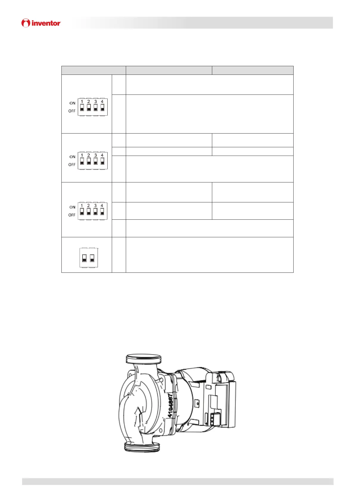
6 Internal Circulation Pump
The pump is controlled via a digital low-voltage pulse-width modulation signal which means that the speed of rotation
depends on the input signal. The speed changes as a function of the input profile. The relationship between external static
pressure and water flow rate is described in Part 2, 7 “Hydronic Performance”.
Figure 3-6.1: Internal circulation pump
1234 1234
S1 S2
ONOFF
12 34
S4
 Loading...