65
Matrix Mono
Part 3 - Installaon and Field Sengs
Matrix Mono
64
Inventor Matrix Mono Engineering Data Book
2.3 Placement Considerations
Placement of the outdoor unit should take account of the following considerations:
Outdoor units should not be exposed to direct radiation from a high-temperature heat source.
Outdoor units should not be installed in positions where dust or dirt may affect heat exchangers.
Outdoor units should not be installed in locations where exposure to oil or to corrosive or harmful gases, such as
acidic or alkaline gases, may occur.
Outdoor units should not be installed in locations where exposure to salinity may occur.
Outdoor units should be installed in well-drained, well-ventilated positions.
Outdoor units should be installed in positions that are as close as possible to the heat emitters.
Outdoor units should be installed in positions that are sufficiently close to the desired position of the wired controller
that the controller’s wiring length limitation will not be exceeded.
In systems that are configured to heat domestic hot water and/or include an external backup electric heater, outdoor
units should be installed in positions that are sufficiently close to the domestic hot water tank and/or backup electric
heater that the temperature sensor wiring length limitations will not be exceeded.
Outdoor units should be installed in locations where the noise from the unit will not disturb neighbors.
2.4 Strong Wind Installation
Wind of 5m/s or more blowing against an outdoor unit’s air outlet blocks the flow of air through the unit, leading to
deterioration in unit capacity, accelerated frost accumulation
when in heating mode or domestic hot water mode, and potential
disruption to operation due to increased pressure in the
refrigerant circuit. Exposure to very strong wind can also cause the
fan to rotate excessively fast, potentially leading to damage to the
fan. In locations where exposure to high winds may occur should
take account of the following considerations:
For installation of the outdoor unit in a place where the wind
direction can be foreseen, refer to Figure 3-2.3 and Table
3-2.1 for installation of the unit. Set the outlet side at a right
angle to the direction of the wind, refer to Figure 3-2.2.
If turn the air outlet side toward the building's wall, fence or screen. Make sure there is enough room to do the
installation
Figure 3-2.3: Installation room illustration
Table 3-2.1: Installation room
requirement (Unit: mm)
Model A(mm)
4-6KW
≥300
8-16KW
≥300
Model B(mm)
4-6KW
≥1000
8-16KW
≥1500
Figure 3-2.2: Strong wind installation direction
Matrix Mono
65
Part 3 - Installation and Field Settings
2.5 Cold Climate Installation
In cold climate locations installation should take account of the following considerations:
Never install the unit at a site where the suction side may be exposed directly to wind.
To prevent exposure to wind, install a baffle plate on the air discharge side of the unit.
To prevent exposure to wind, install the unit with its suction side facing the wall.
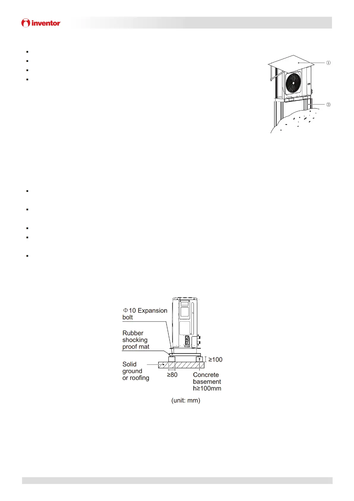
In areas of heavy snowfall, a canopy should be installed to prevent snow entering the
unit. Additionally, the height of the base structure should be increased so as to raise
the unit further off the ground. Refer to Figure 3-2.4.
2.6 Hot Climate Installation
As the outdoor temperature is measured via the outdoor ambient temperature sensor,
make sure to install the outdoor unit in the shade, or a canopy should be constructed to
avoid direct sunlight. So that it is not influenced by the sun’s heat, otherwise system
protection may occur.
2.7 Base Structure
Outdoor unit base structure design should take account of the following considerations:
A solid base prevents excess vibration and noise. Outdoor unit bases should be constructed on solid ground or on
structures of sufficient strength to support the unit’s weight.
Bases should be at least 100mm high to provide sufficient drainage and to prevent water ingress into the base of the
unit.
Either steel or concrete bases may be suitable.
Outdoor units should not be installed on supporting structures that could be damaged by water build-in in the event
of a blocked drain.
Fix the unit securely to foundation by means of the Φ10 expansion bolt. It is best to screw in the foundation bolts
until their length is 20 mm from the foundation surface.
Figure 3-2.5: Outdoor unit typical concrete base structure design (unit: mm)
Figure 3-2.4: Snow shielding
 Loading...