Matrix Mono
76
Inventor Matrix Mono Engineering Data Book
7 User Interface Field Settings
7.1 Introduction
During installation, the Matrix Mono’s settings and parameters should be configured by the installer to suit the
installation configuration, climate conditions and end-user preferences. The relevant settings are accessible
and programmable through the FOR SERVICEMAN menu on the Matrix Mono’s user interface. The user interface
menus and settings can be navigated using the user interface’s touch-sensitive keys, as detailed in Table 3-7.1.
Figure 3-7.1: User interface
Table 3-7.1: User interface keys
Keys Function
MENU Go to the menu structure(on the home page)
◄► ▼ ▲
Navigate the cursor on the display
Navigate in the menu structure
Adjust settings
ON/OFF
Turn on/off the space heating/cooling operation or DHW mode
Turn on/off functions in the menu structure
BACK Come back to the up level
UNLOCK
Long press for unlock/lock the controller
Unlock /lock some functions such as “DHW temperature adjusting”
OK
Go to the next step when programming a schedule in the menu
structure and confirm a selection to enter in the submenu of the menu
structure.
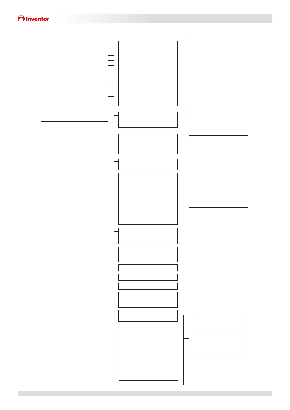
FOR SERVICEMAN
1 DHW MODE SETTING
2 COOL MODE SETTING
3 HEAT MODE SETTING
4 AUTO MODE SETTING
5 TEMP. TYPE SETTING
6 ROOM THERMOSTAT
7 OTHER HEATING SOURECE
8 HOLIDAY AWAY SETTING
9 SERVICE CALL
10 RESTORE FACTORY SETTINGS
11TEST RUN
12 SPECIAL FUNCTION
13 AUTO RESTART
14 POWER INPUT LIMI
TATION
15 INPUT DEFINE
16 CASCADE SET
17 HMI ADDRESS SET
1 DHW MODE SETTING
1.1 DHW MODE
1.2 DISINFECT
1.3 DHW PRIORITY
1.4 DHW PUMP
1.5 DHW PRIORITY TIME SET
1.6 dT5_ON
1.7 dT1S5
1.8 T4DHWMAX
1.9 T4DHWMIN
1.10 t_INTERVAL_DHW
1.11 dT5_TBH_OFF
1.12 T4_TBH_ON
1.13 t_TBH_DELAY
1.14 T5S_DI
1.15 t_DI_HIGHTEMP
1.16 t_DI_MAX
1.17 t_DHWHP_RESTRICT
1.18 t_DHWHP_MAX
1.19 DHW PUMP TIME RUN
1.20 PUMP RUNNING TIME
1.21 DHW PUMP DI RUN
2 COOL MODE SETTING
2.1 COOL MODE
2.2 t_T4_FRESH_C
2.3 T4CMAX
2.4 T4CMIN
2.5 dT1SC
2.6 dTSC
2.7 t_INTERVAL_C
2.8 T1SetC1
2.9 T1SetC2
2.10 T4C1
2.11 T4C2
2.12 ZONE1 C-EMISSION
2.13 ZONE2 C-EMISSION
11 TEST RUN
12 SPECIAL FUNCTION
9 SERVICE CALL
PHONE NO.
MOBILE NO.
4 AUTO MODE SETTING
4.1 T4AUTOCMIN
4.2 T4AUTOHMAX
5 TEMP. TYPE SETTING
5.1 WATER FLOW TEMP.
5.2 ROOM TEMP.
5.3 DOUBLE ZONE
8 HOLIDAY AWAY SETTING
8.1 T1S_H.A._H
8.2 T5S_H.A._DHW
7 OTHER HEATING SOURCE
7.1 dT1_IBH_ON
7.2 t_IBH_DELAY
7.3 T4_IBH_ON
7.4 dT1_AHS_ON
7.5 t_AHS_DELAY
7.6 T4_AHS_ON
7.7 IBH LOCATE
7.8 P_IBH1
7.9 P_IBH2
7.10 P_TBH
6 ROOM THERMOSTAT
6.1ROOM THERMOSTAT
13 AUTO RESTART
13.1 COOL/HEAT MODE
13.2 DHW MODE
3 HEAT MODE SETTING
3.1 HEAT MODE
3.2 t_T4_FRESH_H
3.3 T4HMAX
3.4 T4HMIN
3.5 dT1SH
3.6 dTSH
3.7 t_INTERVAL_H
3.8 T1SetH1
3.9 T1SetH2
3.10 T4H1
3.11 T4H2
3.12 ZONE1 H-EMISSION
3.13 ZONE2 H-EMISSION
3.14 t_DELAY_PUMP
10 RESTORE FACTORY SETTINGS
14 POWER INPUT LIMITATION
14.1 POWER LIMITATION
15 INPUT DEFINE(M1M2)
15.1 ON/OFF(M1M2)
15.2 SMART GRID
15.3 T1B(Tw2)
15.4 Tbt1
15.5 Tbt2
15.6 Ta
15.7 Ta-adj
15.8 SOLAR INPUT
15.9 F-PIPE LENGTH
15.10 RT/Ta_PCB
15.11 PUMPI SILENT MODE
16 CASCADE SET
16.1 PER_START
16.2 TIME_ADJUST
16.3 ADDRESS RESET
17 HMI ADDRESS SET
17.1 HMI SET
17.2 HMI ADDRESS FOR BMS
 Loading...