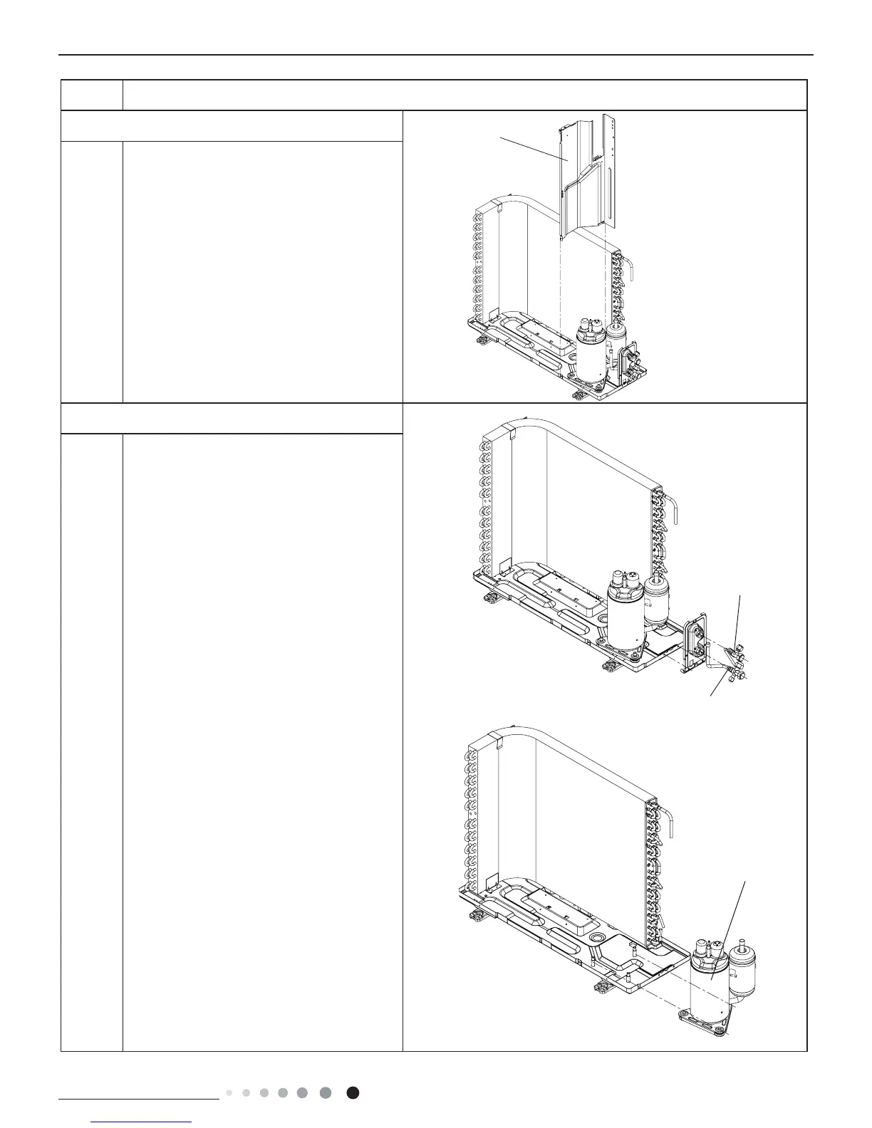
ProcedureStep
Loosen the screws of the Clapboard Sub-
Assy .
The Clapboard Sub-Assy has a hook on
thelower side. Lift and pull the Clapboard Sub-
Assyto remove.
Remove the 3 footing screws of the
compressorand remove the compressor.
11. Remove clapboard sub-assy
Liquid valve
Compressor
Gas valve
12. Remove Compressor
Remove the 2 screws xing the gas valve.
Unsolder the welding spot connecting gas
valveand air return pipe and remove the gas
valve.(Note: it is necessary to warp the gas
valve whenunsoldering the welding spot.)
Remove the 2screws xing liquid valve.
Unsolder the weld-ing spot connecting
liquid valve and remove theliquid valve.
Clapboard
 Loading...