13
INSTALLATIONINSTRUCTIONS
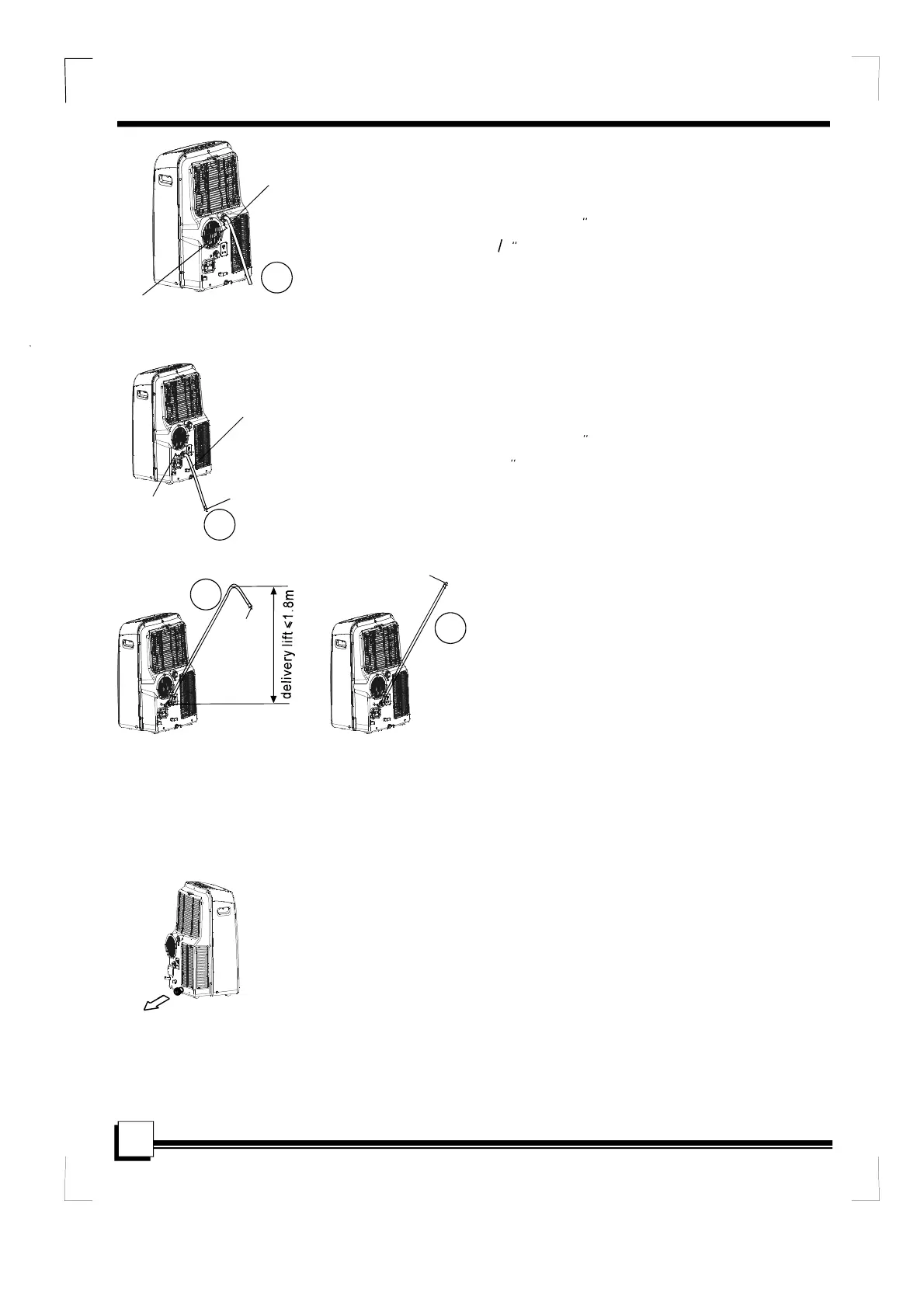
Waterdrainage:
-Duringdehumidifyingmodes,removetheupper
drainplugfromthebackoftheunit,installthedrain
connector(5/8universalfemalemender)with
34hose(locallypurchased).Forthemodels
withoutdrainconnector,justattachthedrain
hosetothehole.Placetheopenendofthe
hosedirectlyoverthedrainareainyourbasement
floor.PleaserefertoFig.20a.
-Duringheatingpumpmode,removethelowerdrain
plugfromthebackoftheunit,installthedrain
connector(5/8universalfemalemender)with
3/4hose(locallypurchased).Forthemodels
withoutdrainconnector,justattachthedrain
hosetothehole.Placetheopenendofthe
hoseadaptordirectlyoverthedrainareainyour
basementfloor.PleaserefertoFig.20b.
-Whenthewaterlevelofthebottomtrayreaches
apredeterminedlevel,
Carefullymovetheunittoadrainlocation,
removethebottomdrainplugandletthe
waterdrainaway(Fig.22).Reinstallthebottom
drainplugandrestartthemachineuntiltheP1
symboldisappears.Iftheerrorrepeats,callfor
service.
""
theunitbeeps8times,
thedigitaldisplayareashowsP1.Atthistime
theairconditioning/dehumidificationprocesswill
immediatelystop.However,thefanmotorwill
continuetooperate(thisisnormal).
""
Removethe
upperdrainplug
Continuous
drainhose
Fig.20a
Fig.20b
Fig.22
NOTE:Besuretoreinstallthebottomdrainplug
beforeusingtheunit.
Removethe
lowerdrainplug
Continuous
drainhose
drainhose
adaptor
NOTE:Makesurethehoseissecuresothereare
noleaks.Directthehosetowardthedrain,making
surethattherearenokinksthatwillstopthewarter
flowing.Placetheendofthehoseintothedrainand
makesuretheendofthehoseisdowntoletthe
waterflowsmoothly.(SeeFig.20a,20b,21a).Do
neverletitup.(SeeFig.21b).
Fig.21a Fig.21b
√
×
√
√
drainhose
adaptor
drainhose
adaptor
 Loading...