Version 1.00 | Optidrive CoolVert User Guide | 17www.invertekdrives.com
3
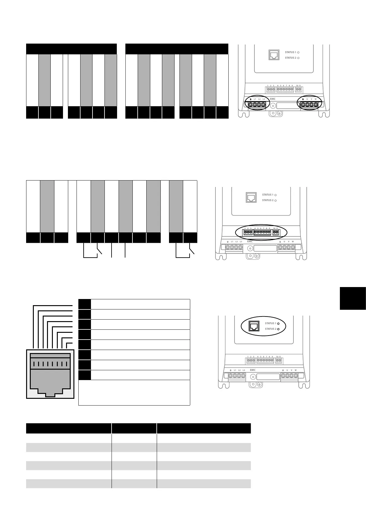
Installation
Power Connections
230V Single Phase Variants 400V 3-Phase Variants
1 2 3 4 5 6 7 8 9
10
11
STATUS 1
STATUS 2
L1 L2 L3 U V WEMC
1 2 3 4 5 6 7 8 9
10
11
STATUS 1
STATUS 2
L1 L2 L3 U V WEMC
1 2 3 4 5 6 7 8 9
10
11
STATUS 1
STATUS 2
L1 L2 L3 U V WEMC
Power Earth / Ground
L1 (200VAC)
Neutral
Power Earth / Ground
Motor U Phase
Motor V Phase
Motor W Phase
Power Earth / Ground
Supply L1
Supply L2
Supply L3
Power Earth / Ground
Motor U Phase
Motor V Phase
Motor W Phase
E
L
N
E
U
V
W
E
L1
L2
L3
E
U
V
W
3.3.3. Control Wiring
The Optidrive Coolvert has pluggable control terminals to support easy installation. There are three pluggable control terminal blocks
split into:
Serial Communications (T1-T3)
Inputs (T5 – T9)
Output Relay (T10 – T11)
0V Common
Modbus TX/RX +
Modbus TX/RX -
+24V Output (100mA)
Digital Input 1
Analogue Input 1
0V Common
STO +
STO -
User Relay A
User Relay B
1 2 3 4 5 6 7 8 9
10
11
STATUS 1
STATUS 2
L1 L2 L3 U V WEMC
1 2 3 4 5 6 7 8 9
10
11
STATUS 1
STATUS 2
L1 L2 L3 U V WEMC
1
2
3
4
5
6
7
8
9
10
11
Run / Stop Speed Ref
RJ45 Port
This port is intended for use with the Optistick Smart for parameter cloning or for connection to the mobile App or to PC Tools or for
Master Follower configuration of drives.
1 Not used
1 2 3 4 5 6 7 8 9
10
11
STATUS 1
STATUS 2
L1 L2 L3 U V WEMC
1 2 3 4 5 6 7 8 9
10
11
STATUS 1
STATUS 2
L1 L2 L3 U V WEMC
2 Not used
3 0 Volts
4 -RS485 (PC)
5 +RS485 (PC)
6 +24 Volt
7 RS 485- Modbus RTU
8 RS 485+ Modbus RTU
Warning:
This is not an Ethernet connection. Do not
connect directly to an Ethernet port.
The RJ45 port has some terminals that are internally connected in parallel with the pluggable control terminals as shown below:
Pluggable Control Terminal RJ45 Terminal Description
1 3 0 Volt Common
2 8 Modbus RTU TX/RX + (RS485)
3 7 Modbus RTU TX/RX - (RS485)
4 6 User +24 Volt (100mA Max)
- 5 PC-Tools TX/RX + (RS485 Optibus)
- 4 PC-Tools TX/RX - (RS485 Optibus)