18 | Optidrive CoolVert User Guide | Version 1.00 www.invertekdrives.com
3
Installation
3.3.4. Safe Torque Off
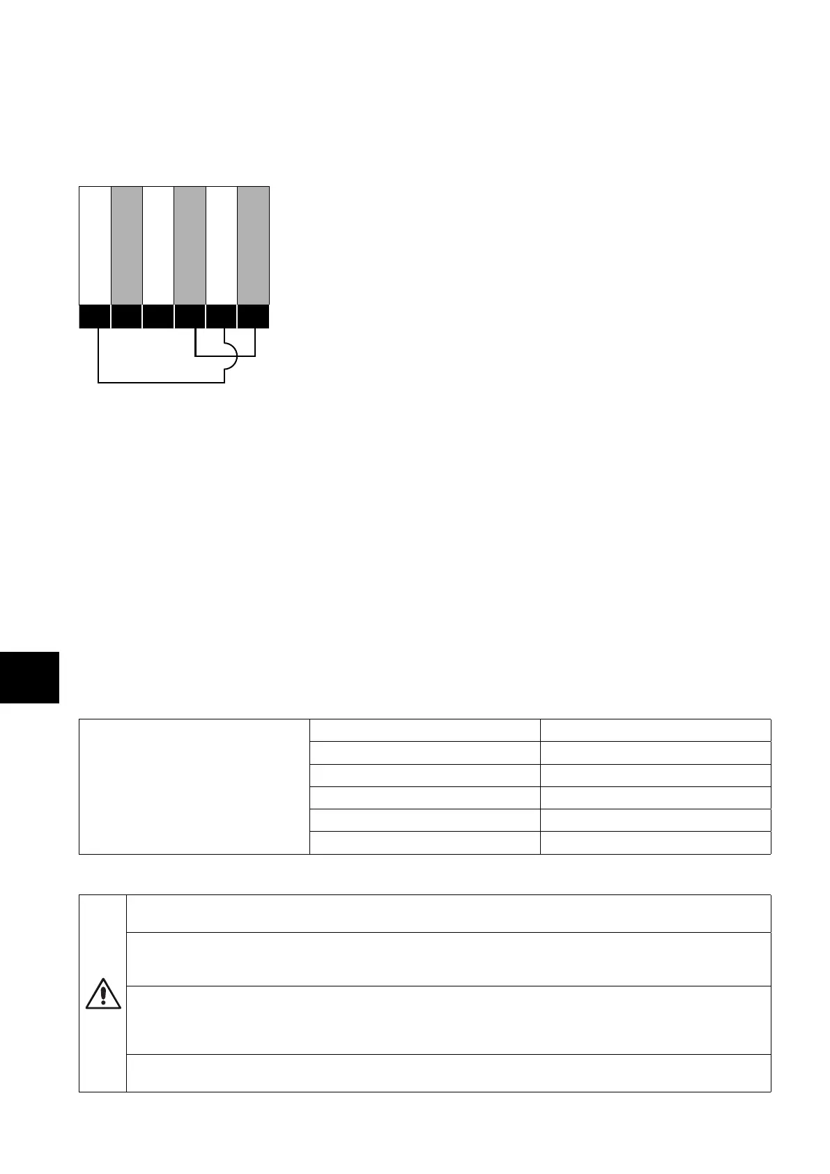
Safe Torque OFF will be referred to as “STO” through the remainder of this section. If the “STO” function is not required in your
installation, you must link out the “STO” circuit by linking terminal 4 to terminal 8 and linking terminal 7 to terminal 9 as shown in the
figure below. Please read the remainder of this chapter for further information about the functionality and limitations of the “STO” circuit.
Showing the links needed if the STO is not required
+24V Output (100mA)
Digital Input 1
Analogue Input 1
0V Common
STO +
STO -
4
5
6
7
8
9
Responsibilities
The overall system designer is responsible for defining the requirements of the overall “Safety Control System” within which the drive
will be incorporated; furthermore the system designer is responsible for ensuring that the complete system is risk assessed and that the
“Safety control System” requirements have been entirely met and that the function is fully verified, this must include confirmation testing
of the “STO” function before drive commissioning. The system designer shall determine the possible risks and hazards within the system
by carrying out a thorough risk and hazard analysis, the outcome of the analysis should provide an estimate of the possible hazards,
furthermore determine the risk levels and identify any needs for risk reduction. The “STO” function should be evaluated to ensure it can
sufficiently meet the risk level required.
What STO Provides
The purpose of the “STO“ function is to provide a method of preventing the drive from creating torque in the motor in the absence of the
“STO“ input signals (Terminal 8 with respect to Terminal 9), this allows the drive to be incorporated into a complete safety control system
where “STO“ requirements need to be fulfilled.
1
The “STO“ function can typically eliminate the need for electro-mechanical contactors
with cross-checking auxiliary contacts as per normally required to provide safety functions.
2
The drive has the “STO“ function built-in as
standard and complies with the definition of “Safe torque off“ as defined by IEC 61800-5- 2:2016. The “STO“ function also corresponds
to an uncontrolled stop in accordance with category 0 (Emergency Off), of IEC 60204-1. This means that the motor will coast to a stop
when the “STO” function is activated, this method of stopping should be confirmed as being acceptable to the system the motor is driving.
The “STO“ function is recognised as a fail-safe method even in the case where the “STO“ signal is absent and a single fault within the drive
has occurred, the drive has been proven in respect of this by meeting the following safety standards.
Safe Torque Off (STO)
IEC 61800-5-2:2016 SIL 3
EN ISO 13849-1:2015 PL “e”
EN 61508 (Part 1 to 7): 2010 SIL 3
EN 60204-1: 2006 & A1: 2009 Cat 0
EN 62061: 2005 & A2: 2015 SIL CL 3
Independent Approval TUV Rheinland
What STO Does Not Provide
Disconnect and ISOLATE the drive before attempting any work on it. The “STO“ function does not prevent high voltages
from being present at the drive power terminals.
1
NOTE The “STO“ function does not prevent the drive from an unexpected re-start. As soon as the “STO“inputs receive the
relevant signal it is possible (subject to parameter settings) to restart automatically, Based on this, the function should not be
used for carrying out short-term non-electrical machinery operations (such as cleaning or maintenance work).
2
NOTE In some applications additional measures may be required to fulfil the systems safety function needs: the “STO“
function does not provide motor braking. In the case where motor braking is required a time delay safety relay and/or a
mechanical brake arrangement or similar method should be adopted, consideration should be made over the required
safety function when braking as the drive braking circuit alone cannot be relied upon as a fail safe method.
When using permanent magnet motors and in the unlikely event of a multiple output power devices failing then the motor
could effectively rotate the motor shaft by 180/p degrees (Where p denotes number of motor pole pairs).