Version 1.00 | Optidrive CoolVert User Guide | 37www.invertekdrives.com
4
Set-up and Operation
4.4.5. Group 5 Parameters & Modbus Registers
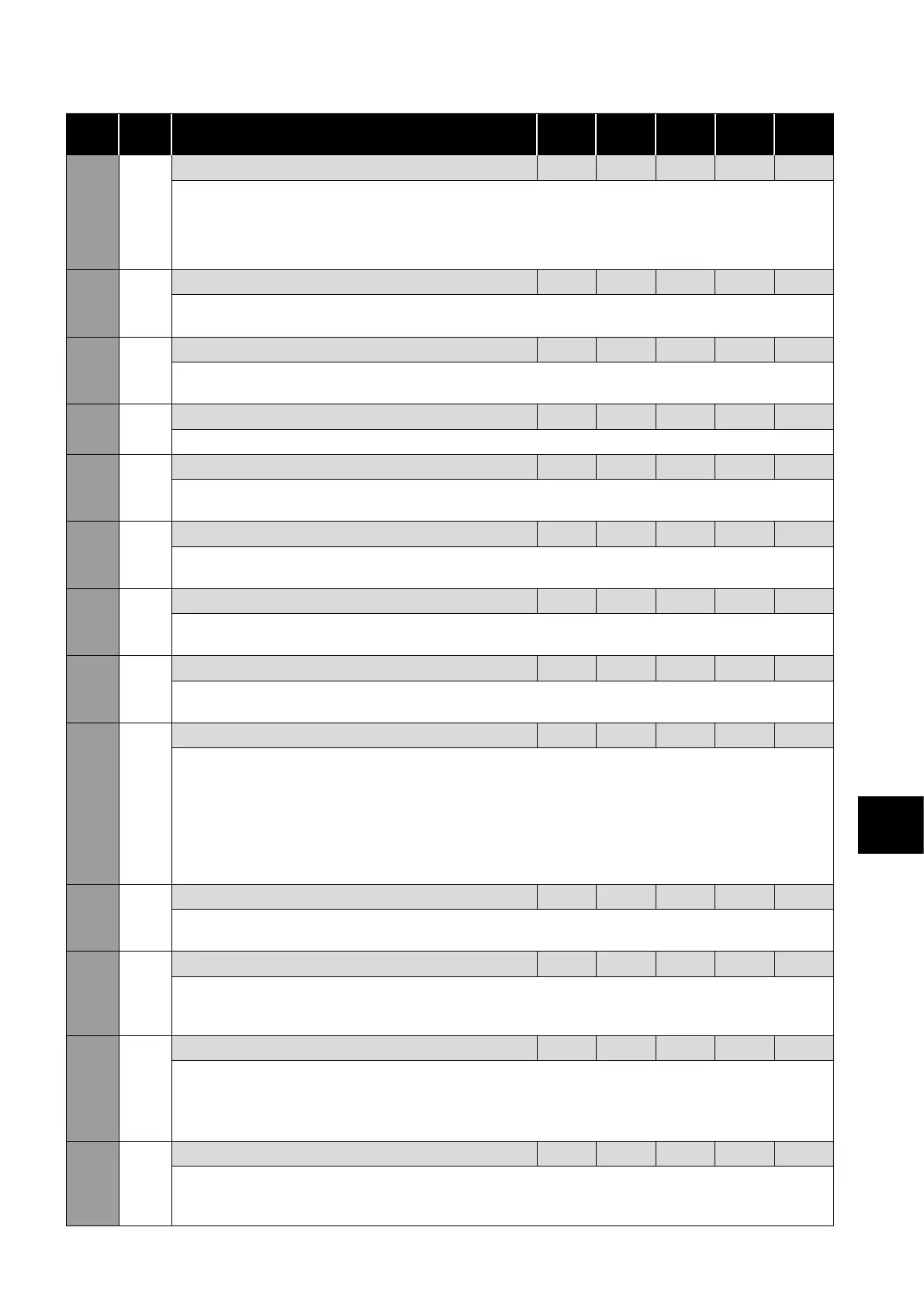
Par
Mod
Add Description Def Min Max Unit R/W
5-01 501 Motor Control Mode 0 0 6 - R/W
0: BLDC vector speed control
1: Permanent Magnet Vector Speed Control
2: Induction Motor Vector Speed Control (CT)
3: Induction Motor Vector Speed Control (VT)
4: Induction Motor V/F
5: Synchronous Reluctance Vector Speed
Control
6: LSPM speed control
5-02 502 Motor Parameter Autotune 0 0 1 - R/W
When set to 1, the drive immediately carries out a non-rotating autotune to measure the motor parameters for
optimum control and efficiency. Following completion of the autotune, the parameter automatically returns to 0.
5-03 503 Vector Speed Controller Proportional Gain 50 0.1 400 % R/W
Sets the proportional gain value for the speed controller when operating in Vector Speed motor control mode
(P5-01 <> 4).
5-04 504 Vector Speed Controller Integral Time Constant 0.050 0.001 2.00 s R/W
Sets the integral time for the speed controller in Vector Speed control mode (P5-01 <> 4).
5-05 505 Motor Power Factor (Cos Ø) dd 0.5 0.99 - R/W
When operating with induction motors in Vector Speed or Vector Torque motor control modes, this parameter
must be set to the motor nameplate power factor before autotuning.
5-06 506
Effective Power Stage Switching Frequency
0 0 6 - R/W
Higher frequency reduces the audible 'ringing' noise from the motor, and improves the output current waveform,
at the expense of increased heat losses within the drive.
5-07 507 Maximum Current Limit 110 20 13 0 % R/W
This parameter defines the maximum current limit used by the drive as a percentage of motor rated current (P1-
07).
5-08 508 Motor Power Limit - - - - R/W
This parameter set’s the power limit of the drive in percentage of drive rating. If this power limit is reached, the
drive will fold back the output frequency to keep within the configured limit.
5-09 509 Motor Thermal Overload Management 0 0 1 - R/W
When Motor Overload Management is enabled, full overload current will be available until the overload
integrator approaches the I.t trip level. At this point, the current limit will be reduced automatically to the maximum
level that can be sustained on a continuous basis.
This will normally result in the speed of the motor automatically reducing. This feature is typically used in
applications where overload trips need to be avoided and a reduction in speed can be accepted.
When Thermal Overload Management is disabled, full overload current will be available until the drive trips on
“It-trP".
5-10 510 Drive Thermal Overload Management 0 0 1 - R/W
When enabled (P5-10 = 1), the drive will automatically set the current limit to 80% of the motor rated current if
the heatsink temperature is greater than 90 degree C.
5-11 511 Motor Thermal Overload Retention Enable 1 0 1 - R/W
When enabled, the motor thermal memory retention function will save the calculated motor thermal history on
drive power down, using this saved value as the starting value on next power up. If this function is disabled, the
motor thermal history is reset to zero on every power up.
5-12 512 Discontinuous Modulation Mode Select 0 0 7 - R/W
0: 3-Pase Modulation.
1: 2-Phase Modulation.
2-Phase modulation mode slightly improves drive efficiency of the drive but can cause more audible noise in the
motor.
5-13 513 Enable Reverse Speed Selection 0 0 1 - R/W
If this parameter is set to 1 (Enabled), it will allow a -ve speed reference to be written by serial communications
to the drive which will cause reverse speed operation. This setting should be kept as 0 (disabled) if prevention of
reverse operation is required.