ELECTRICAL CONNECTION
12
Pulsar extractor fan | Installation and operation instructions
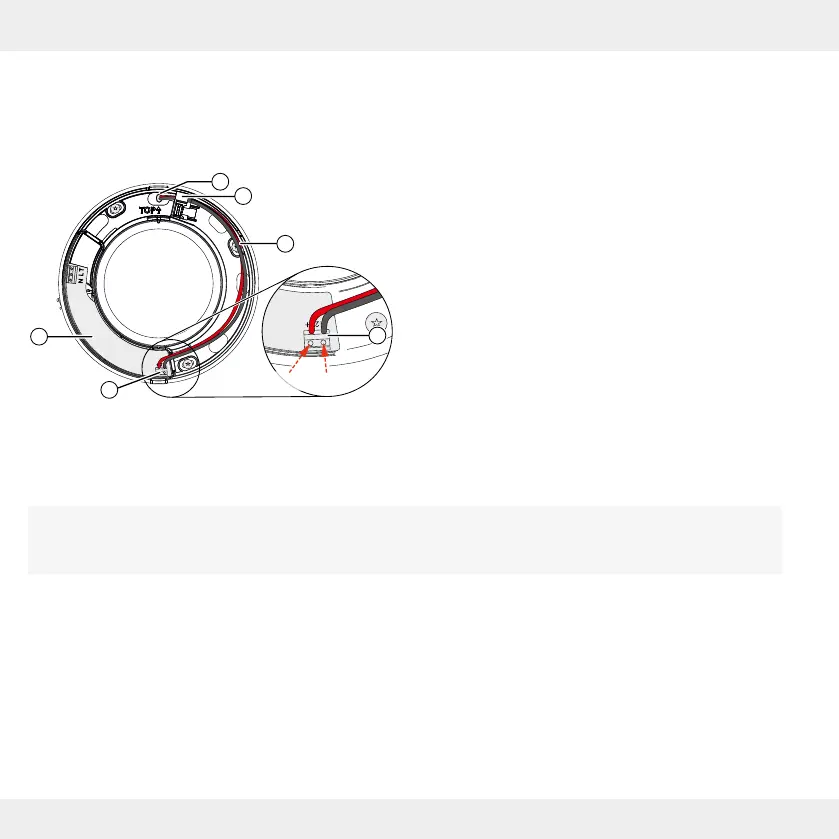
Electrical connection 12 V DC (Direct current)
Connection terminal for operating voltage cable
Terminal assignment
Figure 9: Circuit board – Connection terminal 12 V DC
Wiring diagrams 12 V connection
The connection of the exhaust fan depends on the desired functions. Make sure to connect the exhaust air fan correctly
and select the correct presettings for your functions during commissioning.The switch S1 integrated on the exhaust fan
Pulsar has no function when connecting 12 V DC.
Sensor-controlled, with continuous ventilation:
• Setting must be selected via the inVENTer Mobile
App.
• Continuous ventilation with an air volume ow of
30 m³/h.
• Fan power increases in case of increased humidity
or under the inuence of light changes.
Sensor controlled functions
Sensor-controlled, without continuous ventilation:
• Factory settings to ensure ventilation as required.
• The extractor fan is switched on and o automatically
when there is a change in humidity or when there is
a change in light.
3
2
4
5
+ 12 V GND (– )
1 Cable entry for operating voltage cable
2 Cable gland for operating voltage cable
3 Operating voltage cable, DC 12 V, 2-wire
4 Connection terminal for operating cable
5 Circuit board
4.2


 To Next Page