T
Thomas JohnsonSep 12, 2025
How to fix PCDE error on INVT CHV180-7R5G-4?
- SshawgeorgeSep 12, 2025
If your INVT Inverter displays 'PCDE', it is because the encoder signal wire was connected wrong. Adjust encoder wiring.
How to fix PCDE error on INVT CHV180-7R5G-4?
If your INVT Inverter displays 'PCDE', it is because the encoder signal wire was connected wrong. Adjust encoder wiring.
What does PCE mean on my INVT Inverter?
If your INVT Inverter displays 'PCE', it could be due to a broken encoder signal wire (inspect encoder connection) or a damaged encoder (inspect whether the encoder output signal or not).
Why is my INVT Inverter showing OV3 error?
If your INVT Inverter displays 'OV3', it could be due to abnormal input voltage changes (install input reactor) or high load inertia (add proper braking kits).
What does EEP error mean on INVT CHV180-7R5G-4 Inverter?
If your INVT Inverter displays 'EEP', it could be due to a read/write fault of control parameters (press STOP/RST to reset) or EEPROM damage (ask for support).
What causes TE error on INVT Inverter?
If your INVT Inverter displays 'TE', it could be due to the motor capacity not being compatible with that of the inverter (change the model of the inverter), improper setting of motor rated parameters (set the rated parameters according to the nameplate of the motor), a large offset between the parameters in the autotuning and the standard parameters (empty the motor and reidentify), or overtime of autotuning (check motor’s wiring and the parameters setting).
What to do if my INVT Inverter displays OH1?
If your INVT Inverter displays 'OH1', it indicates a sudden overcurrent. Refer to the overcurrent solution. Other causes include a short-circuited output phase (reconfigure), a damaged ventilation duct or fan (clear the duct and change the fan), high ambient temperature (reduce it), loose wiring on the control board (check and rewire), damage to the assistant circuit causing undervoltage (ask for support), a direct bridge arm issue in the power module (ask for support), or an abnormal control board (ask for support).
What does CE error mean on INVT CHV180-7R5G-4 Inverter?
If your INVT Inverter displays 'CE', it could be caused by an improper baud rate setting (select proper baud rate), receiving wrong data (press STOP/RST to reset and ask for support), or communication being interrupted for a long time (check communication devices and signals).
What to do if my INVT CHV180-7R5G-4 Inverter shows ITE error?
If your INVT Inverter displays 'ITE', it could be due to loose wires or connectors on the control board (check the connector and rewire), a damaged assistant circuit (ask for support), a damaged Hall sensor (ask for support), or an abnormal amplifying circuit (ask for support).
Why does my INVT CHV180-7R5G-4 Inverter trip the input switch when running?
If your INVT Inverter displays 'The inverter displays normally when power on, but switch at the input side trips when running', inspect whether the output side of inverter is short circuit. If yes, ask for support. Inspect whether ground fault exists. If yes, solve it. If trip happens occasionally and the distance between motor and inverter is too far. It is recommended to install output AC reactor.
What should I do if my INVT Inverter is running but the motor won’t move?
If your INVT Inverter displays 'Motor doesn’t move after inverter running', inspect if there is balanced three-phase output among U, V, and W. If yes, then motor could be damaged, or mechanically locked. Please solve it. If the output is unbalanced or lost, the inverter drive board or the output module may be damaged. ask for support.
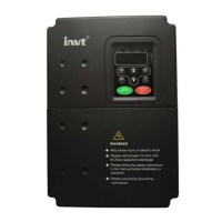
| Power | 7.5 kW |
|---|---|
| Voltage | 380-480 V |
| Frequency Range | 0-400 Hz |
| Protection Level | IP20 |
| Cooling Method | Forced air cooling |
| Input Voltage | 380-480 V |
| Operating Temperature | -10°C to +50°C |
| Storage Temperature | -20 to 65°C |
| Humidity | 5-95% (non-condensing) |
| Altitude | Up to 1000m |
| Efficiency | 98% |
Provides a standard wiring diagram for inverter installation and connections.
Explains the procedures and considerations for wiring the main circuits of the inverter.
Details precautions and procedures for wiring the control circuit terminals of the inverter.
Provides guidelines for installing the inverter to ensure electromagnetic compatibility (EMC).
Explains the function of each button and indicator on the inverter's operating keypad.
Details the procedures for setting parameters and performing operations like autotuning.
Configures multi-step speed settings and S-curve parameters for elevator acceleration and deceleration.
Defines motor parameters like type, voltage, current, and power factor for optimal performance.
Configures parameters for vector control, including PID settings for speed loops.
Sets encoder type, pulse number, and direction selection for encoder feedback.
Provides a table of fault codes, types, reasons, and solutions for diagnosing and resolving inverter issues.
Guides on system debugging, including autotuning, overhaul running, and S-curve adjustment.
Explains multi-step speed and analog quantity speed tracking running modes for elevator operation.
Configures multi-step speed settings and S-curve parameters for elevator acceleration and deceleration.
Defines motor parameters like type, voltage, current, and power factor for optimal performance.
Configures parameters for vector control, including PID settings for speed loops.
Sets encoder type, pulse number, and direction selection for encoder feedback.
Sets protection parameters like phase-failure, overload, and over-speed deviation detection.