Goodrive300-01A series VFD for air compressor Commissioning instruction
-22-
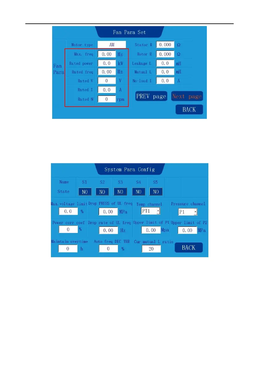
Figure 4-8 Fan parameter setup interface
Step 3: Click Next page to enter System Para Config or click BACK to return to system
configuration. On the system configuration interface, click System Para Config. S1 functions as
emergency-stop switch, select NO/NC based on the polarity of the emergency-stop switch, as shown
in Figure 4-9.
Figure 4-9 System parameter configuration interface
Set pressure sensor parameters, temperature sensor parameters and specialized function
parameters according to system sensor configuration. Then, click BACK to enter the system
configuration page.
Step 4: On the system configuration interface, click One-key to Set Para. The system completes the
related parameter configuration automatically.
Step 5: On the system configuration interface, click Debug Mode. The page shown in Figure 4-10 is
displayed.

 Loading...


