Goodrive350-19 series VFD Product overview
- 7 -
3 Product overview
3.1 What this chapter contains
This chapter introduces the VFD running principles, features, layout, nameplate, and model
instructions.
3.2 Basic principle
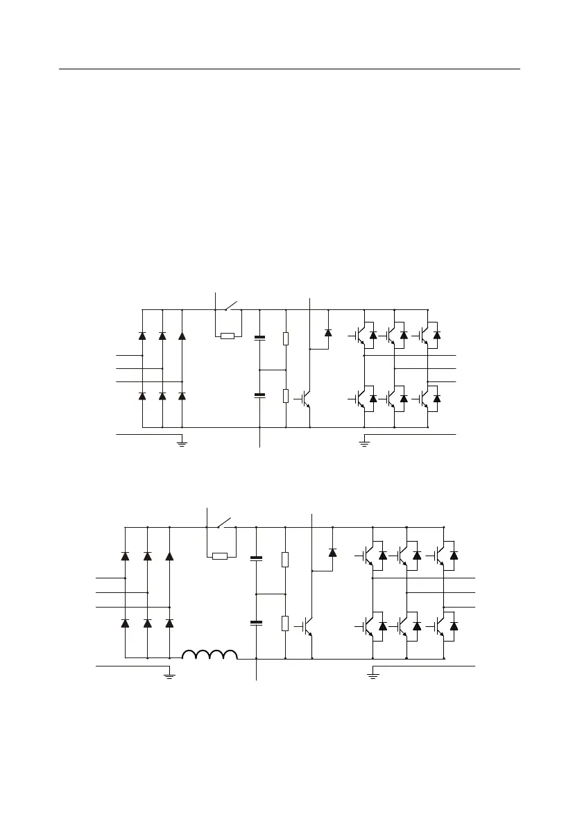
Goodrive350-19 series VFDs are used to control asynchronous AC induction motors and
permanent-magnet synchronous motors. The following lists the main circuit diagrams of the VFDs.
The rectifier converts 3PH AC voltage into DC voltage, and the capacitor bank of intermediate circuit
stabilizes the DC voltage. The inverter converts DC voltage into the AC voltage used by an AC motor.
When the circuit voltage exceeds the upper limit, the external braking resistor is connected to the
intermediate DC circuit to consume the feedback energy.
Figure 3.1 Main circuit diagram for 380V 15kW or lower VFD models
Figure 3.2 Main circuit diagram for 380V 18.5kW–110kW VFD models

 Loading...


