Goodrive350-19 series VFD Installing
- 32 -
4.4 Standard wiring of control circuit
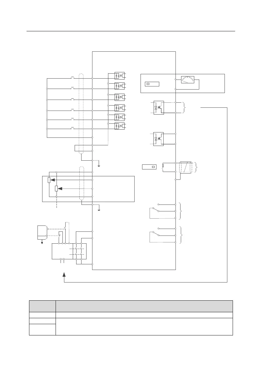
4.4.1 Wiring diagram of basic control circuit
+24V
PE
COM
S4
S3
S2
S1
HDIB
PW
HDIA
Forward running
Reverse running
Fault reset
+10V
AI1
AI2
GND
PE
-10V
(External)
GD350-19 series VFD
AO1
V I
SW2
GND
Analog output
0-10V/0-20mA
Y1
CME
COM
HDO
High-speed pulse output and open
collector output are available for
choice.
485+
485-
485G
RS485
communication
RO2C
RO2B
RO2A
RO1C
RO1B
RO1A
Relay 1 output
Relay 2 output
ON
OFF
SW3
Multi-function analog input
Power used for
frequency setting
H1
H2
+24V
S2
S1
Safety controller
Open
circuit
Safety input
Safety switch
Y1 output
Safety state
feedback
Figure 4.18 Wiring diagram of control circuit
Locally provided +10.5V power supply
1. Input range: AI1 voltage/current can choose 0–10V / 0–20mA; AI2: -10V –
+10V;
2. Input impedance: 20kΩ during voltage input; 250Ω during current input;

 Loading...


