Goodrive350-19 series VFD Installing
- 26 -
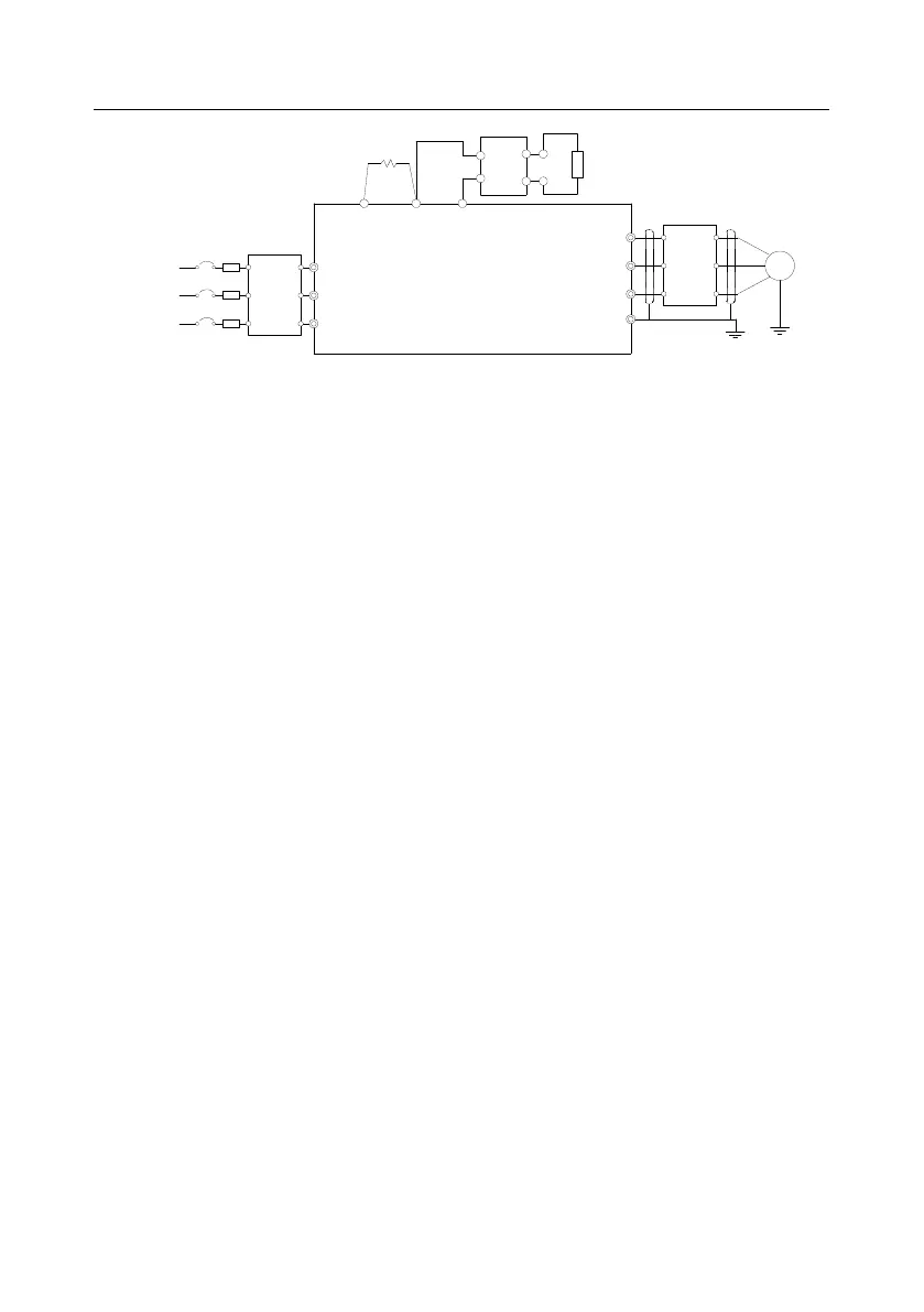
R
S
T
W
V
U
PE
M
VFDs of 22kW and higher
P1
(+)
DC reactor
3PH power
660V±15%
50/60Hz
(-)
Input
reactor
Input
filter
Fuse
DC-
Braking
resistor
DC+
Braking unit
Output
reactor
Output
filter
Figure 4.8 Main circuit wiring diagram for the VFD models of AC 3PH 520V(-15%)–690V(+10%)
Note:
The fuse, DC reactor, braking resistor, input reactor, input filter, output reactor and output filter are
optional parts. For details, see "Optional peripheral accessories".
P1 and (+) have been short connected by default. If the VFD needs to connect to an external DC
reactor, remove the short connector between P1 and (+).
When the braking resistor needs to be connected, remove the yellow warning labels marked with
(+) and (-) from the terminal block before connecting the braking resistor wire. Otherwise, poor
contact may result.
 Loading...


