Goodrive350-19 series VFD Installing
- 36 -
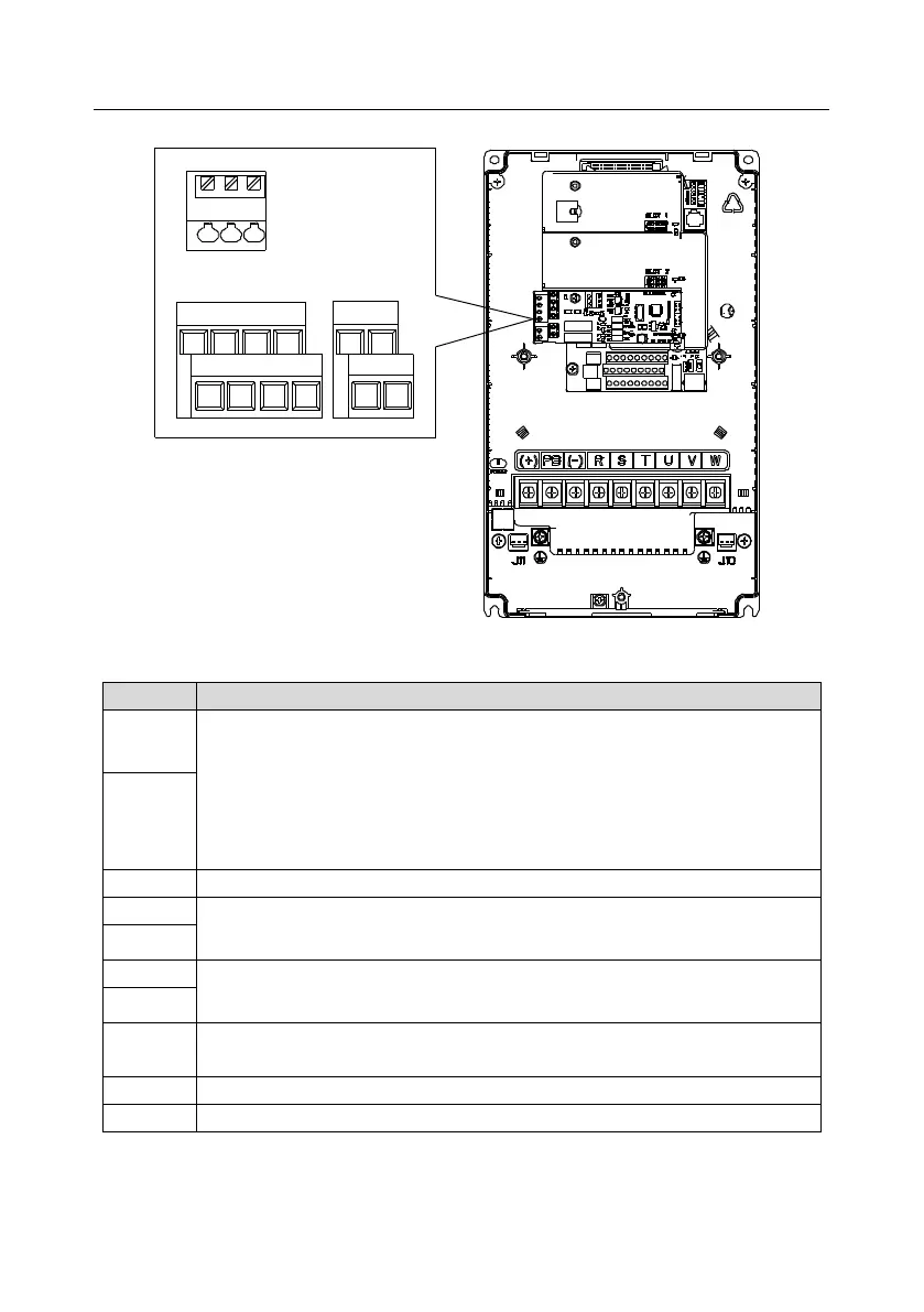
PT 1 +
S5
PT 2 +
S7 R0 4 A R0 4 C
S8
PT -
S6
R0 3 CR0 3 ACO MCO MPW+2 4 V
Figure 4.23 Terminal layout of I/O extension card 2
Independent PT100 and PT1000 inputs: PT1+ connects to PT100 resistor, while
PT2+ connects to PT1000 resistor
1. Resolution: 1°C
2. Range: -20°C–150°C
3. Detection precision: 3°C
4. Supporting disconnection protection
Reference zero potential of PT100/PT1000
RO3 relay output; RO3A is NO, RO3C is common terminal
Contact capacity: 3A/AC250V, 1A/DC30V
RO4 relay output; RO4A is NO, RO4C is common terminal
Contact capacity: 3A/AC250V, 1A/DC30V
Used to provide input digital working power from the external to the internal
Voltage range: 24(-20%)–48VDC(+10%), 24(-10%)–48VAC(+10%) voltage input
User power provided by the VFD; maximum output current 200mA
 Loading...


