Goodrive350-19 series VFD Extension cards
-466-
LED6/7
(Network port status
indicator)
PROFINET communication card and
PC/PLC have been connected via a
network cable
PROFINET communication card and
PC/PLC have not been connected yet
LED8/9
(Network port
communication
indicator)
PROFINET communication card and
PC/PLC are communicating
PROFINET communication card and
PC/PLC are not yet communicating
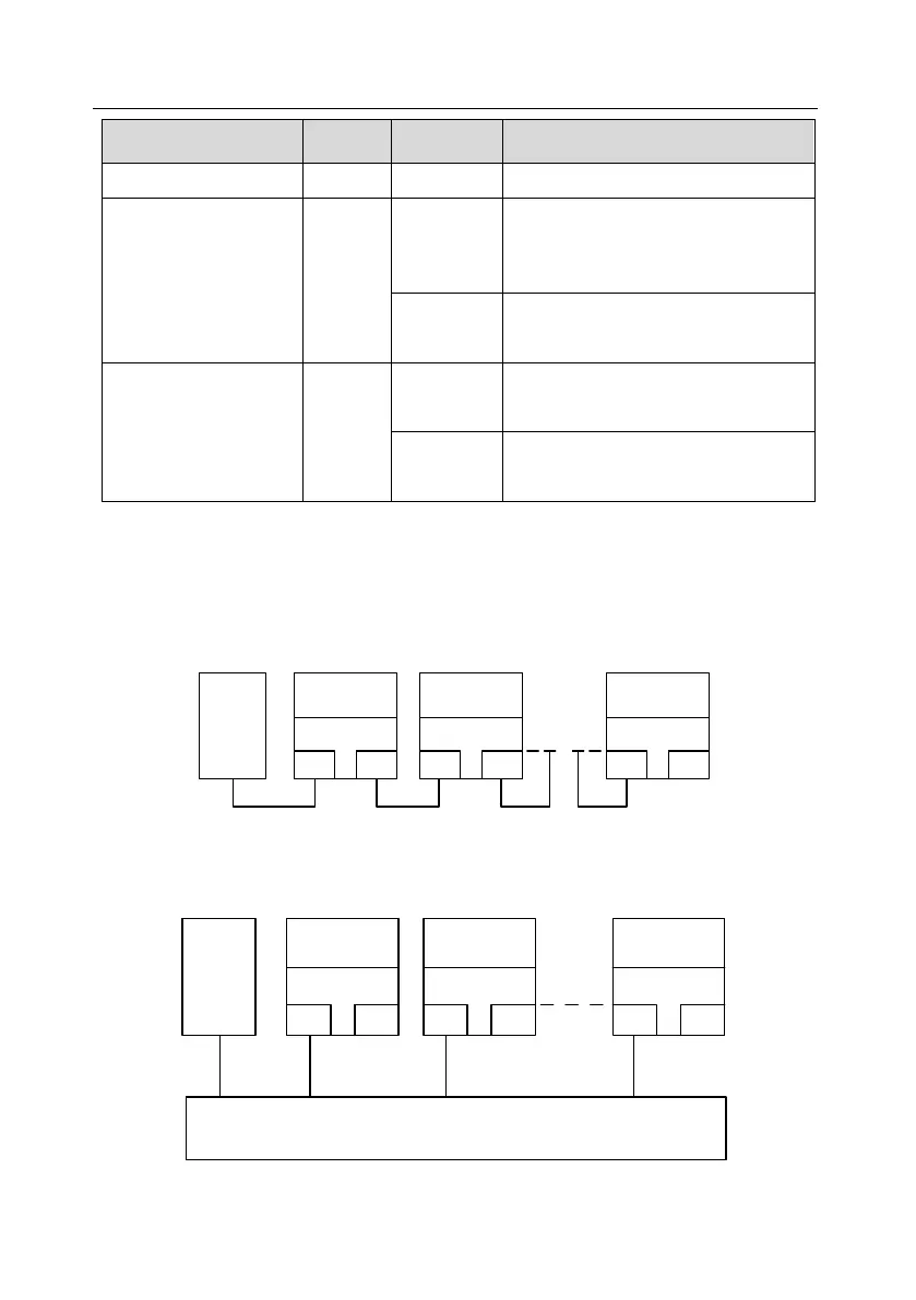
The electrical connection is described as follows:
The Profinet communication card adopts a standard RJ45 interface, which can be used in a linear
network topology and a star network topology. The linear network topology electrical connection
diagram is shown as follows.
Master
device
Slave device 2
RJ45
RJ45
Slave device 1
RJ45
RJ45
Slave device n
RJ45
RJ45
Linear network topology electrical connection diagram
Note: For the star network topology, you need to prepare Profinet switches.
The star network topology electrical connection diagram is shown as follows:
Master
device
Slave device 2
RJ45
RJ45
Slave device 1
RJ45
RJ45
Slave device n
RJ45
RJ45
Switch
 Loading...


