EasyManuals Logo

INVT Goodrive350-19 Series User Manual

INVT Goodrive350-19 Series
540 pages
To Next Page IconTo Next Page
To Previous Page IconTo Previous Page
Page #472 background imageLoading...
Page #472 background image
Goodrive350-19 series VFD Extension cards
-465-
two RJ45 interfaces are not distinguished from each other and are interchangeably swappable. They
are arranged as follows:
Pin
Name
Description
1
TX+
Transmit Data+
2
TX-
Transmit Data-
3
RX+
Receive Data+
4
n/c
Not connected
5
n/c
Not connected
6
RX-
Receive Data-
7
n/c
Not connected
8
n/c
Not connected
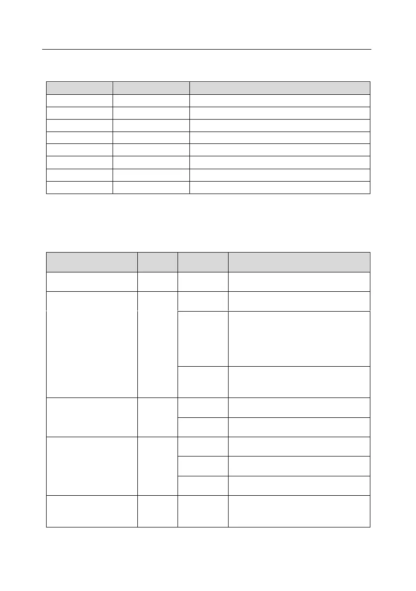
The indicators are described as follows:
The PROFINET communication card has 9 indicators, of which LED1 is the power indicator, LED2–5
are the communication status indicators of the communication card, and LED6–9 are the status
indicators of the network port.
LED
Color
State
Description
LED1
Green
3.3V power indicator
LED2
(Bus status indicator)
Red
On
No network connection
Blinking
The connection to the network cable
between the Profinet controller is OK,
but the communication is not
established.
Off
Communication with the Profinet
controller has been established
LED3
(System fault indicator)
Green
On
Profinet diagnosis exists
Off
No Profinet diagnosis
LED4
(Slave ready indicator)
Green
On
TPS-1 protocol stack has started
Blinking
TPS-1 waits for MCU initialization
Off
TPS-1 protocol stack does not start
LED5
(Maintenance status
Green
Manufacturer-specific - depending on
the characteristics of the device

Table of Contents

Questions and Answers:

Question and Answer IconNeed help?

Do you have a question about the INVT Goodrive350-19 Series and is the answer not in the manual?

INVT Goodrive350-19 Series Specifications

General IconGeneral
BrandINVT
ModelGoodrive350-19 Series
CategoryDC Drives
LanguageEnglish

Related product manuals