48
LBK System| Instruction manual v1.3 SEP 2019 |LBK-System_instructions_en v1.3|© 2018-2019 Inxpect SpA
7.2.7 Connect the controller to the sensors and assign the IDs
1. Start the Inxpect Safety application.
2. Click Settings and then Sensor ID Nodes.
3. Connect the desired sensor directly to the controller or to the last sensor on the chain.
Note: connect a sensor without an assigned ID (ID = 0) to the controller one at a time.
4. Click ASSIGN ID NODES and follow the instructions on the display.
Note: to reassign the sensors with the default ID 0, click RESET ID NODES.
5. Repeat step 4 for all the sensors, then conclude the procedure.
6. Insert the termination connector into the free connector of the sensor/sensors at the end of the chain.
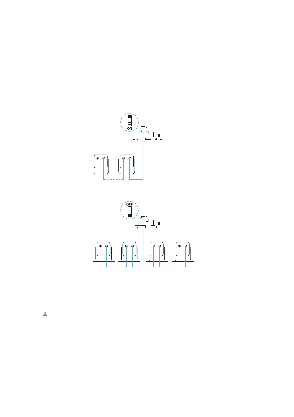
Set the DIP switch of the controller based on its position in the chain. See "Chain examples" below.
7.2.8 Chain examples
Chain with controller at the end of the chain and a sensor with termination connector
Chain with controller inside of the chain and two sensors with termination connector
7.2.9 Save and print the configuration
1. In the Inxpect Safety application, click APPLY CHANGES: the sensors will memorize the inclination set
and the surrounding environment. The application will transfer the configuration to the controller, and
once transfer is complete it will generate a configuration report.
2. Click to save and print the report.
3. If necessary, complete the report with the inclination and height data of the sensors.
4. Require a signature by the authorized person.
7.2.10 Install the side guards
Note: valid procedure for linear barrier applications with limited restart prevention function.
1. Calculate the installation distance of the guards, referring to the values in the configuration report:
(Actual length - BARRIER LENGTH) / 2.
2. Position the guards at the distance calculated in step 1.
7. Installation and use procedures