9
2.3. CEM120 Mount Basic Cable Connection
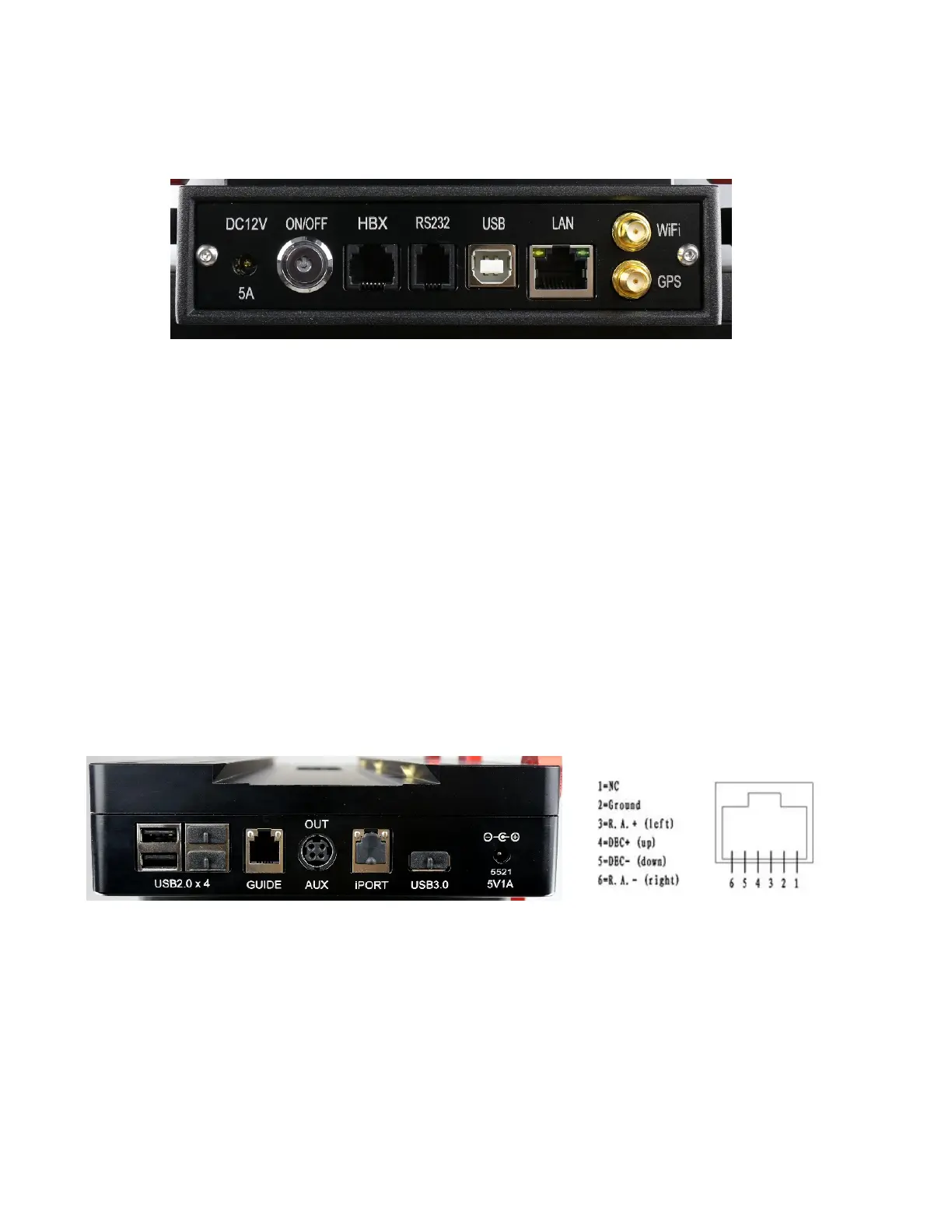
The basic cable connection ports of a CEM120 mount are all located on the mount base, as
shown in Figure 2.
Figure 2. Ports on a CEM120 mount base
DC 12V 5A: DC power socket to power the mount (2.5mmX5.5mm, 5525)
ON/OFF: Power Switch
HBX (Hand Box): For connecting to an 8407 Hand Controller
RS232: Serial port for mount computer control and firmware upgrade
USB: USB port for mount computer control
LAN: network connection for remote control
WiFi: Mini coaxial cable connector for WiFi antenna
GPS: Mini coaxial cable connector for GPS external antenna
2.4. CEM120 Cable Management
The CEM120 mount has a pre-wired Cable Management System that allows the user to connect
their accessories and imaging equipment without cables tangling or snagging when the mount is
slewing or tracking. The Cable Management Outputs are located at the back of the dovetail saddle, as
shown below.
Figure 3. Connects at the end f the dovetail saddle
Figure 4. GUIDE port wiring
At the end of the dovetail saddle, there are
USB 2.0 x 4: 4 USB 2.0 ports with standard type A connectors for connecting accessories
(un powered). They were connected to the USB2.0 input on Input Panel.
GUIDE: port for autoguiding with ST-4 cable. The wiring is shown in Figure 4.
AUX (OUT): A DIN-422 port for high power or other connection purpose. It is connected to
the AUX (IN) port on Input Panel.