Digital488 User’s Manual 11-28-01 Introduction, 1-5
General
Configuration:
Four 8-bit ports, programmable as inputs or outputs. Also included are programmable
handshake lines, data latching capability, Clear and Trigger outputs, and a Service Request (SRQ)
input.
Dimensions:
101.6mm square x 16.51mm high (4” square x 0.65” high)
Weight: 0.13 kg. (0.29 lbs).
Operating Environment:
Standard: Indoor, 0° to 50°C; 0 to 70% RH to 35°C. Linearly derate 3% RH/°C from 35 to 50 °C.
Controls:
IEEE parameter switches.
Indicators:
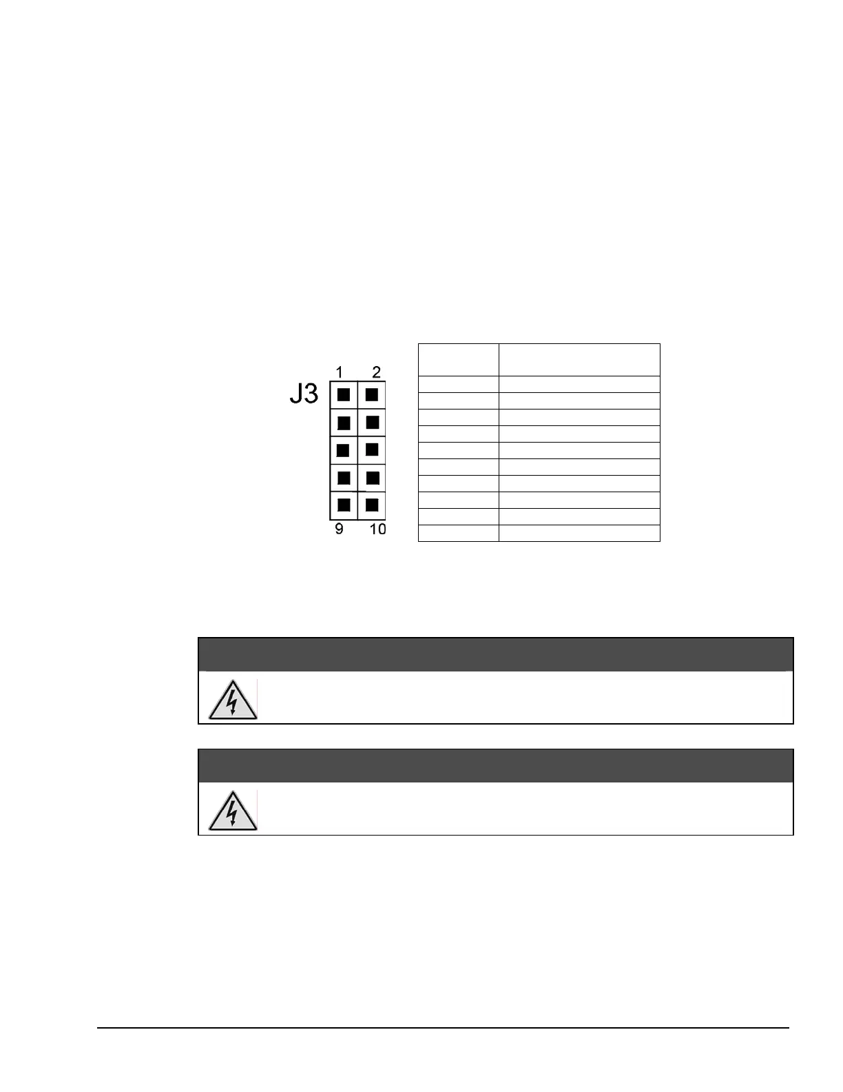
On-board and 10 pin header for remote use. The external LEDs are connected to VCC through a
resistor network. The pin-out table for the LED status header is located in Figure 1.1.
PIN #
LED CONNECTOR
1 Error (Cathode)
2 Error (Anode)
3 SRQ (Cathode)
4 SRQ (Anode)
5 Listen (Cathode)
6 Listen (Anode)
7 Talk (Cathode)
8 Talk (Anode)
9 Power (Cathode)
10 Power (Anode)
Figure 1.1: LED Indicators
Power:
User supplied +5 volts ±0.25% at 1 amp. Mating power connector with 8-inch leads provided.
WARNING
Do not use this interface outdoors. The interface is intended for indoor use only.
Outdoor conditions could result in equipment failure, bodily injury, or death.
CAUTION
Never disassemble the interface case while it is connected to the AC power line.
Internal voltage potentials exist which could cause bodily injury or death.