External Data Ready [EDR] (Digital488: Pin 46
Digital488/32/OEM: Pin 36)
The External Data Ready [EDR] line is an edge sensitive input which is used to latch input data. It is used
in conjunction with the Data Ready command (R1). The EDR signal must be at least 1 microsecond wide
and must have a rise and fall time of less than one microsecond. The EDR line is normally rising-edge
sensitive but can be programmed with the Invert command (I32) to be falling-edge sensitive.
Refer to the following diagram for timing relationships.
When using the EDR line with the R1 command, data is not read when the Digital488 is addressed to talk
as with R0. The Digital488 will only output data when the EDR line transitions.
EDR is not functional in the high-speed binary (F5) format.
Inhibit (Digital488: Pin 44
Digital488/32/OEM: Pin38)
The Inhibit output is asserted while data on the selected I/O port is being read into the I/O port buffer.
This line is normally active high but may be programmed active low by the Invert command (I1).
The Inhibit line can be programmed independent of any I/O operations with the Inhibit command (Qn).
Refer to the following diagram for timing relationships.
The Inhibit line is asserted once for each data read operation for all format [Fn] modes except high-speed
binary [F5]. In this mode, it is asserted for the first data read after the Digital488 is addressed to talk.
On the last data-byte transfer, the data is read again with Inhibit asserted in anticipation of another data
transfer. If Inhibit is used to sequence external hardware, you should be aware that this line will pulse N+1
times; where N is the number of total (5 byte) data transfers.
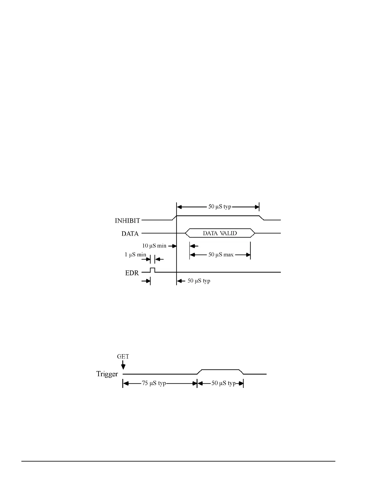
Timing Diagram for EDR Input and Inhibit Output
Trigger (Digital488: Pin 43
Digital488/32/OEM: Pin34)
The Trigger output is pulse for approximately 50 microseconds after a GET (Group Execute Trigger)
command is received from the bus controller. The trigger pulse is normally active high, but can be made
active low with the Invert command (I2). The Handshake command (H2) can independently pulse the
Trigger line, independent of any bus activity.
Timing Diagram for Trigger Output
2-6, Getting Started 11-19-01 Digital488 User’s Manual