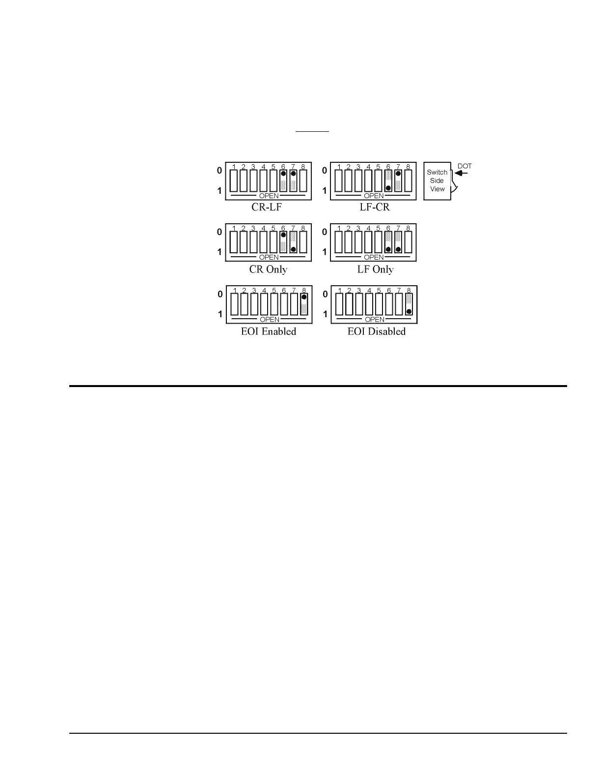
IEEE 488 Bus Output Terminator Selection
The terminating characters sent on output by the Digital488 are determined by SW1-6 through SW1-8.
The terminator switches are read only at power on, but can be changed by the controller through the
Terminator command. If power is cycled after receipt of the Terminator command, then the unit will
again default to the switch settings. The factory default settings are Carriage Return - Line Feed with EOI
asserted.
The Digital488 ignores all terminators received from the bus controller. Only the Execute command (X)
is used to signal the Digital488 that a command string has been completed.
SW1 View for Terminator Selection
Digital Input/Output Ports
The Digital488 has 40 data lines, which can be programmed in groups of 8 as either input or output.
At power on, all 40 bits are in the input mode. Each 8 bit group is one port, beginning with Port 1 as the
least significant 8 bits, and Port 5 as the most significant 8 bits.
The Digital488/32/OEM has 32 data lines, which can be programmed in groups of 8 as either input
or output. Each 8 bit group is one port, beginning with Port 1 as the least significant 8 bits,
and Port 4 as the most significant 8 bits.
Logic Levels
The data and handshake output lines will drive two TTL loads. In addition, ports 1 and 2 outputs are 5 Volt
CMOS compatible. All input lines are less than 1.5 TTL loads. All inputs are protected against damage due
to high static voltages. Normal precautions should be taken to limit the input voltages to -0.3 to +7.0 volts.
All I/O lines are referenced to COMMON (Pin 50).
Digital488 User’s Manual 11-19-01 Getting Started, 2-3