Control Lines
Six control lines enable handshaking of digital I/O data transfer to the Digital488. They are automatically
activated with the corresponding I/O activity and can be independently activated with the
Handshake (Hn) command. Note that the pin numbers for the Digital488/32/OEM are different from
the pin numbers for the Digital488.
Clear (Digital488: Pin 41
Digital488/32/OEM: Pin 33)
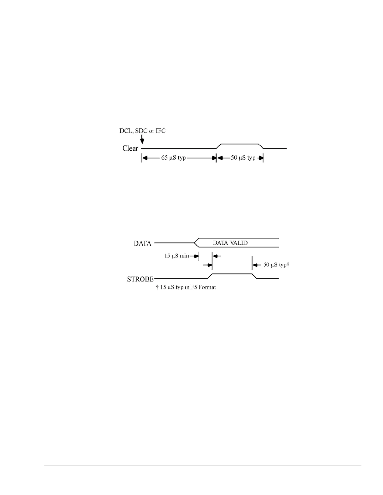
The Clear output is pulse for approximately 50 microseconds after a Device Clear (DCL), Selected Device
Clear (SDC), or Interface Clear (IFC) command has been sent on the bus. The Clear line is normally active
high. The Invert command (I8) will program it active low. The Handshake command (H0) can pulse the
Clear line, independent of any I/O operations.
Timing Diagram for Clear Output
Data Strobe (Digital488: Pin 42
Digital488/32/OEM: Pin 37)
The Data Strobe output is pulse for approximately 50 microseconds after new data is output on the
I/O port. The Data Strobe line is normally active high but may be programmed active low by the Invert
command (I4). The Handshake command (H1) can pulse the Data Strobe line, independent
of an I/O operation.
Timing Diagram for Strobe Output
Digital488 User’s Manual 11-19-01 Getting Started, 2-5