M920 & M920W pH/Dual ORP Controller Owner’s Manual
14
8. Conver ng from Cord to Permanent Connec on
a. Remove cover.
b. Loosen strain relief gland from AC cord.
c. Using a 3/32” (2.44mm) slot screw driver, carefully loosen
terminals that a ach the AC cord to the controller box.
d. Remove the AC cord.
e. Replace the AC cord with a minimum jacketed cord of 18/3 AWG
SW 105º 900 V, then carefully hand- ghten the terminals on the
strain relief gland. Note: For liquid ght installa on connec ons,
replace the strain relief gland with a liquid ght connector and
use a minimum stranded wire gauge of 18 AWG 105º 600 V (do
not use solid conductor) for each conductor: Black (hot), White
(common), and Green (ground).
Important:
The minimum allowable conductor size is 18 AWG
with an ampacity of 10 AMPS, and a ground fault
interrupt circuit breaker of 15-20 AMPS.
Use stranded copper wire only.
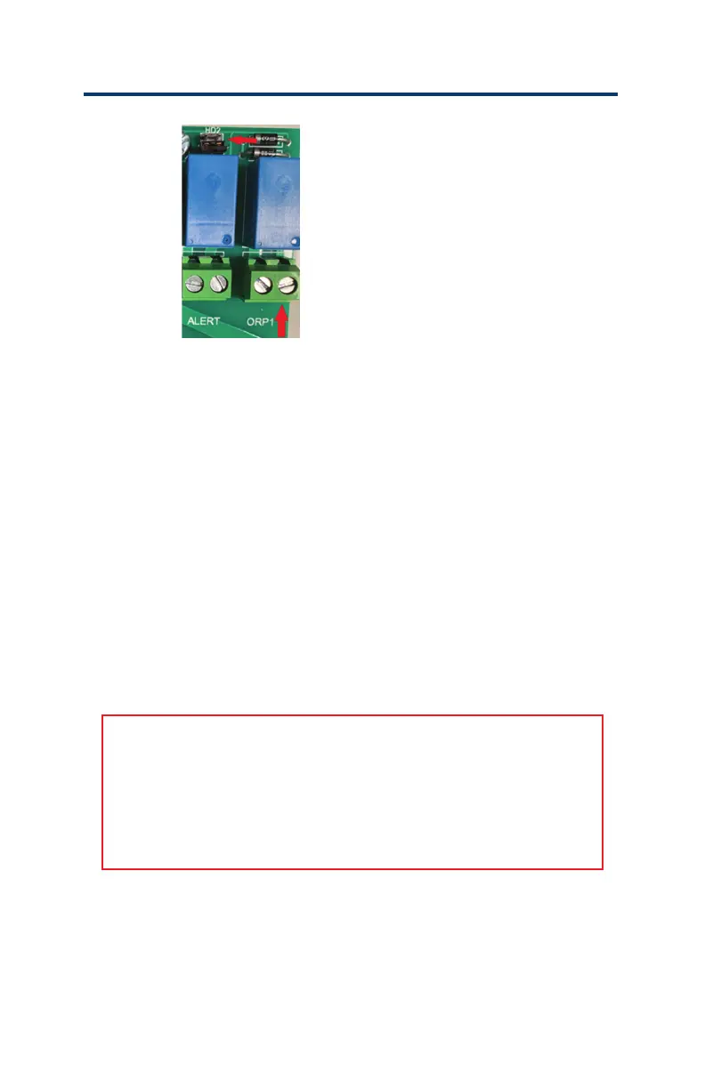
Figure 4: HD2 Jumper
9. Con nue to the next sec on for the connec on requirements for
remote monitoring. The remote monitoring module and the Internet
are needed to complete this process.