4.
22
Iridium Openport Terminal I 4 Installation
Signal
Interference
around the ADE
The ships radar and high power transmitters may cause signal
interference. To avoid possible damage to the ADE and degradation of
ADE performance the unit must be mounted as far away as possible from
these units. In addition it should also be kept clear of other sources of
interference such as other Iridium or Inmarsat terminals.
The diagrams and tables below are only guidelines as the minimum
distances will be dependent on the exact transmitter characteristics as
well as reections from masts, decks and other items in the vicinity of the
ADE. The tables below are to avoid damage and are not necessarily
sufcient for correct operation.
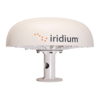
X-band (~ 3cm / 10 GHz) and C-band (4-8GHz) radars
Radar Power
Min distance at 15º
vertical separation
Min distance at 60º
vertical separation
0 – 10kW 0.8 m (2.6 ft.)
0.4 m (1. ft.)
0kW 2.4 m (7.9 ft.) 1.2 m (.9 ft.)
50kW 4.0 m (1.1 ft.) 2.0 m (6.6 ft.)
Table 4 I 2 Minimum Distance from X-band and C-band Radars
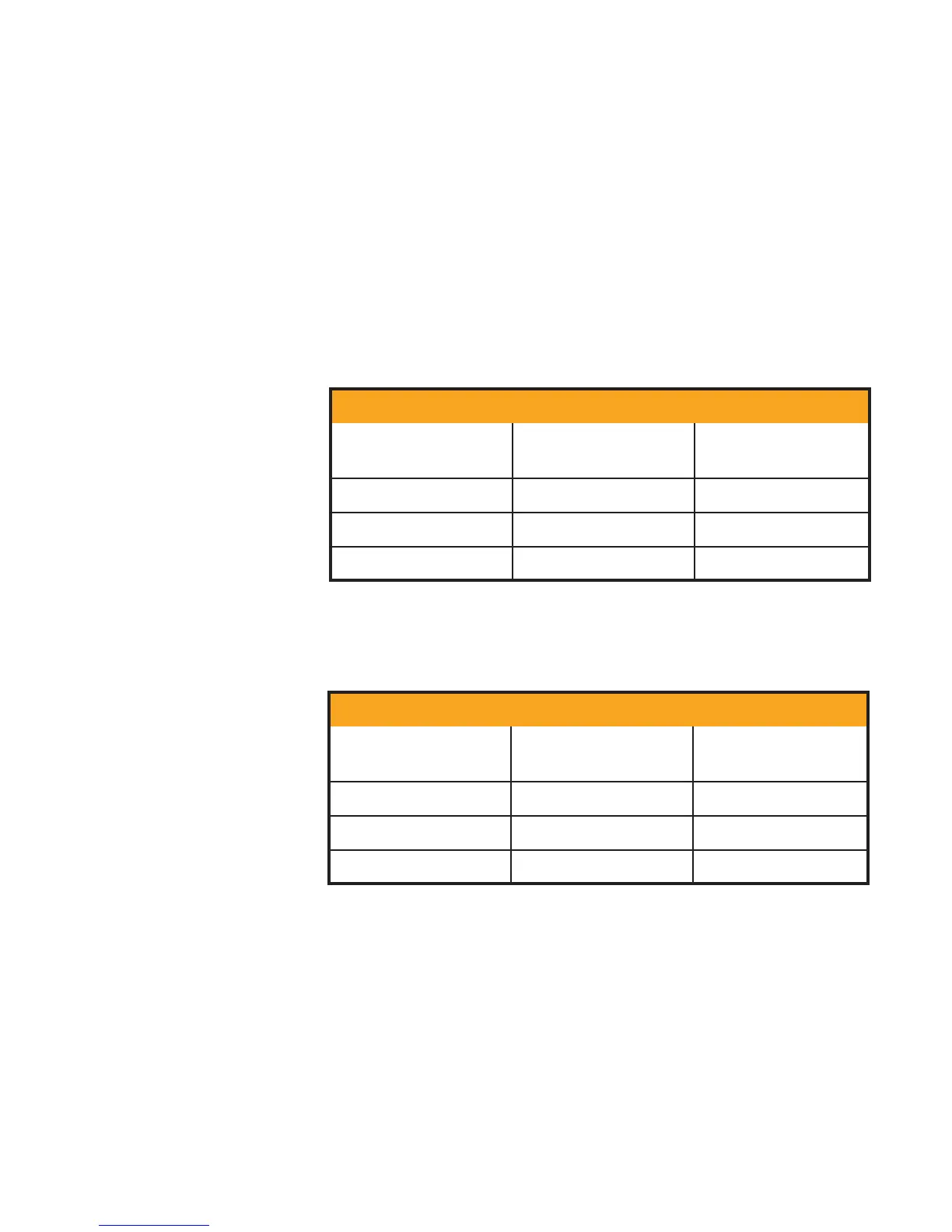
S-band (~ 10cm / 3 GHz) radars
Radar Power
Min distance at 15º
vertical separation
Min distance at 60º
vertical separation
0 – 10kW
0.4 m (1. ft.) 0.4 m (1. ft.)
0kW 1.0 m (. ft.) 0.5 m (1.6 ft.)
50kW 2.0 m (6.6 ft.)
1.0 m (. ft.)
Important! A vertical separation of 15º is always required from any
radar.
Table 4 I 3 Minimum Distance from S-band Radars