SIM
on / off
data
voice 1
voice 2
voice 3
POWER
STATUS
SIGNAL
GPS
4.9
Installing the
BDE
After a suitable location has been chosen, mount the BDE:
1 Layout the locations for the mounting screws, total. The BDE is
mounted with the connector edge facing down. Use the included
template as a guide for drilling the mounting holes.
2 Drill and tap holes for M4 ange style mounting screws
Note: Alternative screws or screw / washer combination may be used.
The ange must t into a 4.5 mm (.18 in.) hole.
4 Hold and screw the BDE against the wall.
5 Remove the SIM cover (retain)
6 Switch the ON/OFF switch in to the OFF position
7 Remove installation cover from bottom left hand corner of BDE
(retain cover and screw)
8 Connect internal cables:
a Fit power feed (either AC or DC) to power connector on BDE, use
strain relief provided within BDE. The power LED should light
Amber.
b Fit cable from ADE to BDE, use strain relief provided within BDE
9 After checking that all the connections are securely made and have
strain relief, replace and fasten the installation cover.
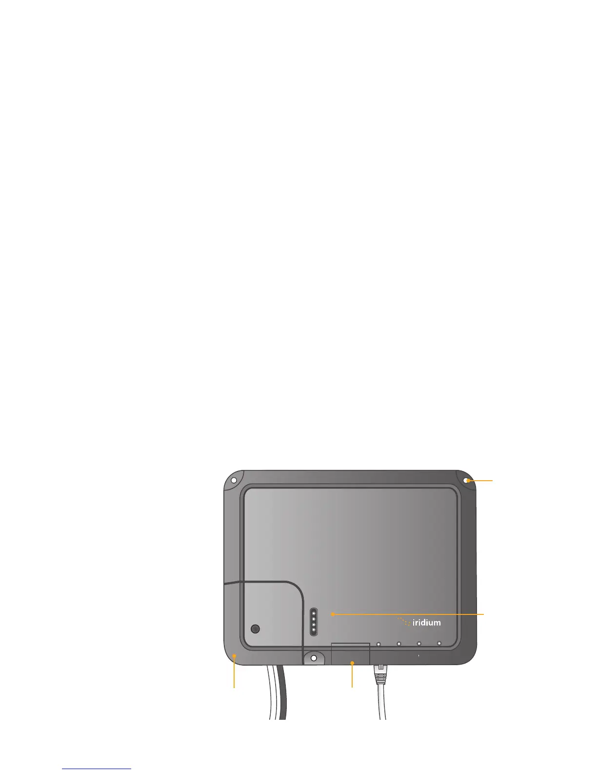
Figure 4 I 4
Mounting
hole
SIM cover
Installation
cover
Power LED
Iridium Openport Terminal I 4 Installation