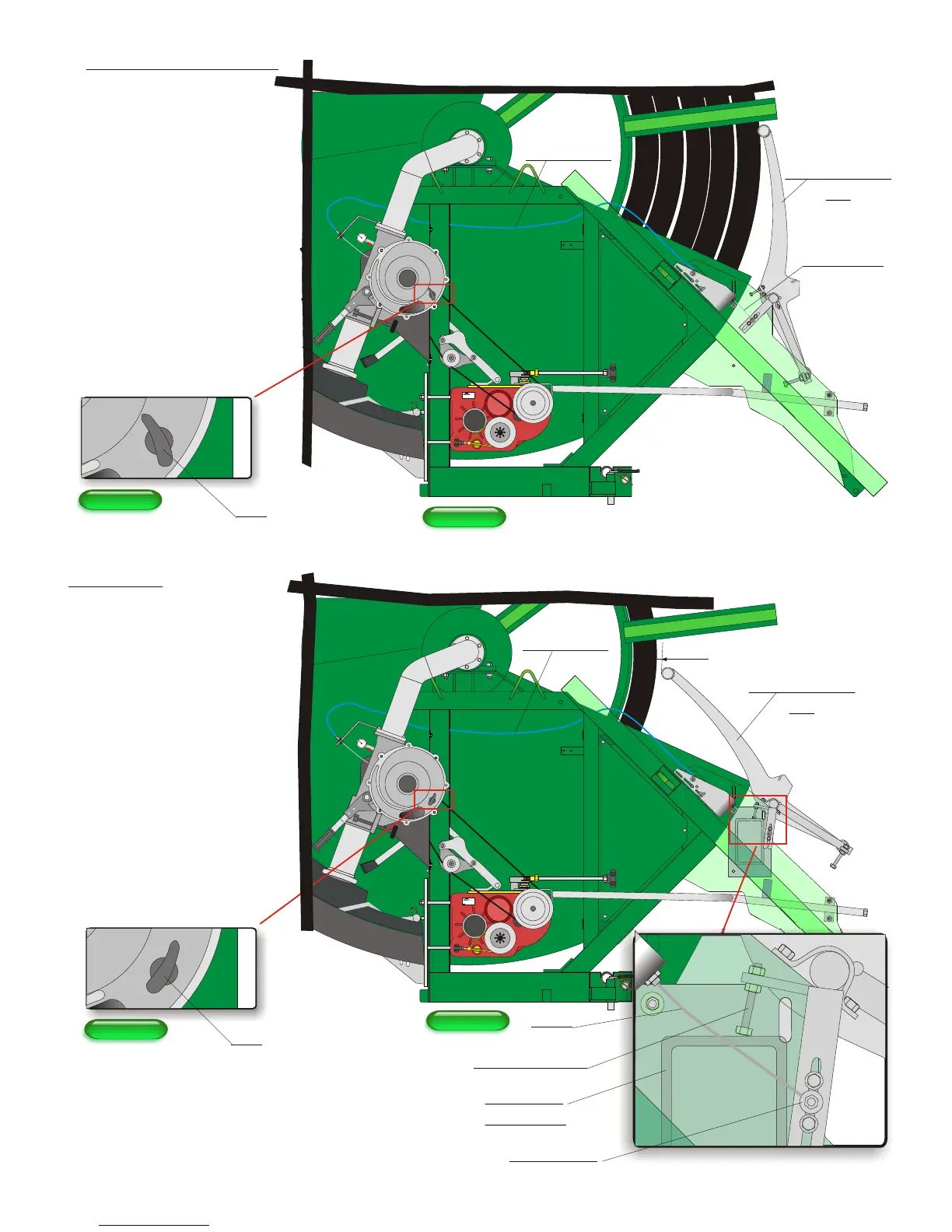
Hose retention
bar
Flap
1 cm
Cable
Adjusting screw
Hoseguide
mechanism
Fig. 50Fig. 50
- Adjustment
- Unbolt the cover of the
turbine. With the tube rolled
up, the flap must be nearly
90° compared to the flow
of water. (fig.49)
Cable screw
- With the tube unwound,
the flap must be parallel
compared to the flow of
water (fig.51) With the
adjusting screw stop,
the hose retention bar 1cm
from the tube (fig.50)
- Adjust the position of the attachment
of the cable so that when the hose retention bar
passes the position (fig.48) to (fig.50), the flap
passes the position (fig.49) to (fig.51).
Fig. 51Fig. 51
- C) Speed compensation:
Fig. 48Fig. 48
Flap
Outer cable
Hose retention
bar
Inner Cable
- The changing of the spool
diameter due to
the coils of tube makes
the speed vary during the
cycle. It is necessary to
compensate for the
variation. This is the role of
the turbine flap.
- During winding, the
hose retention bar follows
the PE tube. Its movement
is transmitted to the flap by
the cable.
Fig. 49Fig. 49
Page 28
Outer cable
 Loading...