INSTALLING AND WIRING
THE CONTROLLER
-
CONTINUED
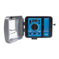
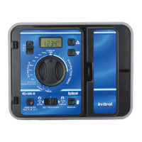
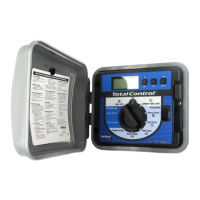
This section includes instructions for installing the controller and
hooking up the electricity. To ensure safe operation, it is important to
follow the instructions carefully. The following topics are covered:
l Selecting the site
l Mounting the controller
l Connecting the power
l
Hooking up the valves
-Testing the valve hook-ups
l
Hooking up a pump start relay
l
How the backup system works
l
Installing and using sensor ports
l
How the electronic circuit breaker works
CAUTION:
To avoid injury to you or damage to the controller,
you MUST follow the sequence of installation steps
outlined in this manual.
SELECTING THE SITE
The controller comes in an outdoor, rain-resistant, rust-resistant and
dust-resistant box. Selecting the correct location for your controller is
essential to ensure safe operation. Select a site for the controller that is:
1.
Away from direct sprinkler spray.
2.
In a shaded and dry location, if possible. Avoid direct sun; do not
expose to temperatures exceeding 130°F.
3. NOT in a closed and humid environment, or where it is subject to
continual heavy condensation.
4. Accessible to a
3-wire,
grounded 120-volt AC, 60 Hz power supply.
4
Installing
&
Wiring the Controller
MOUNTING THE CONTROLLER
WALL MOUNT: For wall mounting, install the controller vertically
on a flat, secure surface. Use the enclosed template to locate mounting
screw holes. Follow complete mounting instructions on template.
PEDESTAL: For free-standing installation on a pedestal, follow the
installation instructions in the pedestal box.
CONNECTING THE POWER
The controller is a solid-state microcomputer that may be affected by
transient surges and electromagnetic interference. Wherever possible,
the controller should be installed on its own dedicated circuit breaker.
CAUTION:
Be
sure to follow all applicable local electrical
wiring codes.
CAUTION:
DO NOT install the controller on the same line or
within 15 feet of a heavy inductive load, such as a
pump, motor, air conditioner, refrigerator, trans-
former, etc. Valve and power wires must also be
routed away from “high power users.”
CAUTION:
DO NOT turn on the power until all valves are
wired (see “Hooking Up the Valves,” page 7).
1.
Remove the lower panel by unfastening the screw located in the
middle of the panel and lifting the panel out and down.
2.
Verify that th
e
yellow and red wires of the transformer are connected
to the
24-volt
AC input on the terminals of the controller (see
figure
1,
page 6). Connect the black and white wires of the 120 volt
AC, 60 Hz power supply to the black and white wires of the trans-
former (see figure 1).
CAUTION:
DO NOT wire 120 volts directly to the PC board
terminals; the transformer supplied with the control-
ler MUST be used.
Installing
&
Wiring the Controller
5

 Loading...


