RANGE
OUTPUT
CURRENT
A
OUTPUT
VOLTAGE
V
OUTPUT
POWER
VA
LOAD
TIME
min
RECOVERY
TIME
min
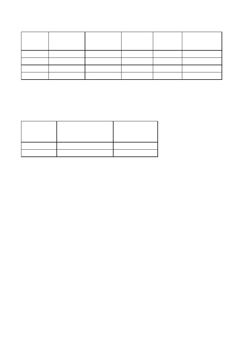
10 A 5 90 450 STEADY
-
10 80 800 3 15
250 V 0,5 250 125 STEADY
1 220 220 3 9
As you see, on the 10 A output it is possible to reach 5 A in
continuous generation; on the 250 V output it is possible to reach
0,5 A in continuous generation. The following table summarizes the
range choice as a function of the total resistance.
RANGE TOTAL
RESISTANCE
Ohm
TEST
CURRENT
A
10 A Up to 200 0.5 to 5 A
250 V More than 200 0.1 to 1 A
For the connection, use the cables and spikes optionally provided.
A) Output connection:
. A single-pole cable for the connection to the local grounding net,
10 m long, section 2.5 sq. mm, plus clamp.
. A single-pole cable for the connection from the test set to the
connection reel, 4 m long, section 2.5 sq. mm.
. A single-pole cable for the connection to the auxiliary dispersion
spike, 100 m long, section 2.5 sq. mm. Wound on a wheel.
. One or two auxiliary dispersion spikes, with screw for insertion
into the ground. Complete with connector to the power cable from
the generator. The upper part, that will protrude from the ground,
is isolated with rubber.
. In case of two spikes, to connect them, a single-pole cable for
the connection from the test set to the connection reel, 4 m long,
section 2.5 sq. mm
. Handle to screw the spike into the ground.
B) Measurement connection:
. A single-pole cable for the connection to the local grounding net,
10 m long, section 2.5 sq. mm, plus clamp.