2.2 EARTH RESISTANCE
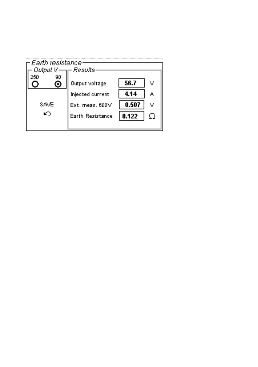
When this test is selected, the following menu is displayed.
Purpose of the test is to measure the soil resistance of systems,
with the neutral isolated or connected to ground via an
impedance, whose short-circuit current does not exceed 500 A, as
per the IEC 80 standard.
In case of fault in the plant, the fault current is the source
voltage divided by the source impedance plus the soil or earth
resistance. The voltage at which the plant arrives with respect to
a far ground is the fault current by the soil resistance: the lower
the resistance, the lower the voltage at which operators can be
subject.
The test is performed by applying the test current to the
grounding net of the system under test, and closing the loop by
an auxiliary earth connection. As we are dealing with a system
with a big dimension, the first problem is that the auxiliary earth
connection must be located far away from the system under test.
If D id the larger dimension of the area (for a four-sided area, the
longer diagonal), the auxiliary earth connection should be located
at a distance greater than d = 5*D from the center of the area.