. A single-pole cable for the connection from the test set to the
measurement reel, 4 m long, section 2.5 sq. mm.
. A single-pole cable for the connection of the meter to the
reference voltage probe, 50 m long, section 1 sq. mm. Wound on a
wheel.
. One test probe to measure the voltage drop; material: zinc-
plated iron; length: 0.5 m. Complete with connector for the
measurement cable.
Once the connection is performed, press START and slowly
increase the output current, to a value close to the maximum
allowed by the output. The display shows:
. The applied test voltage;
. The injected current;
. The voltage drop between the system earth connection and the
voltage spike;
. The corresponding earth resistance.
Now it is necessary to move the voltage spike, as said before,
until the resistance measurement does not change very much: this
is the earth resistance of the system. Once the result is achieved,
press SAVE and slowly reduce to zero the current.
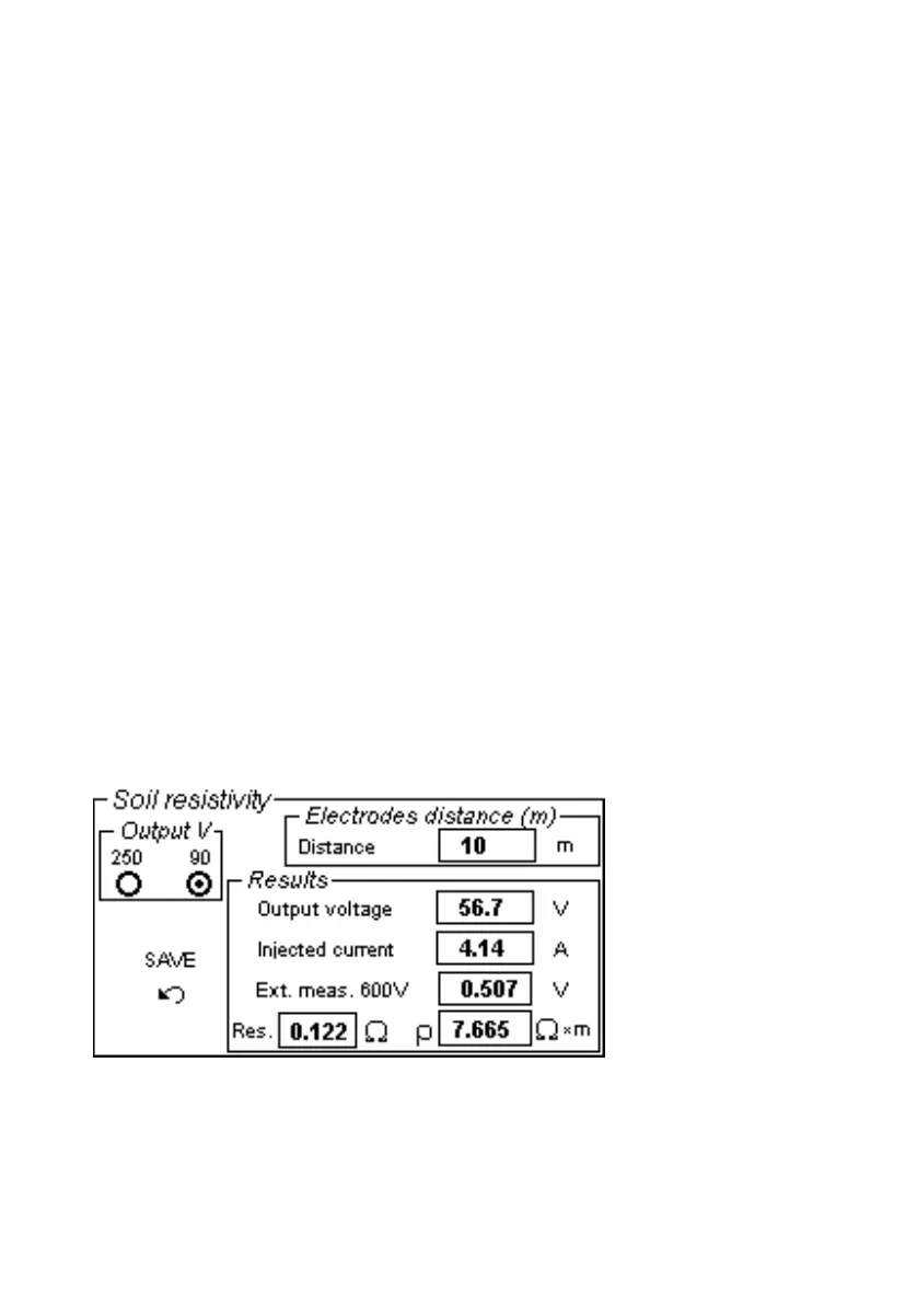
2.3 SOIL RESISTIVITY
When this test is selected, the following menu is displayed.
Purpose of the test is to measure resistivity of the soil where the
plant is to be sited, in order to be able to design the earth
connection grid.