ICP 3020 / ICP 4030 iMC-P Operating instruction
page 13
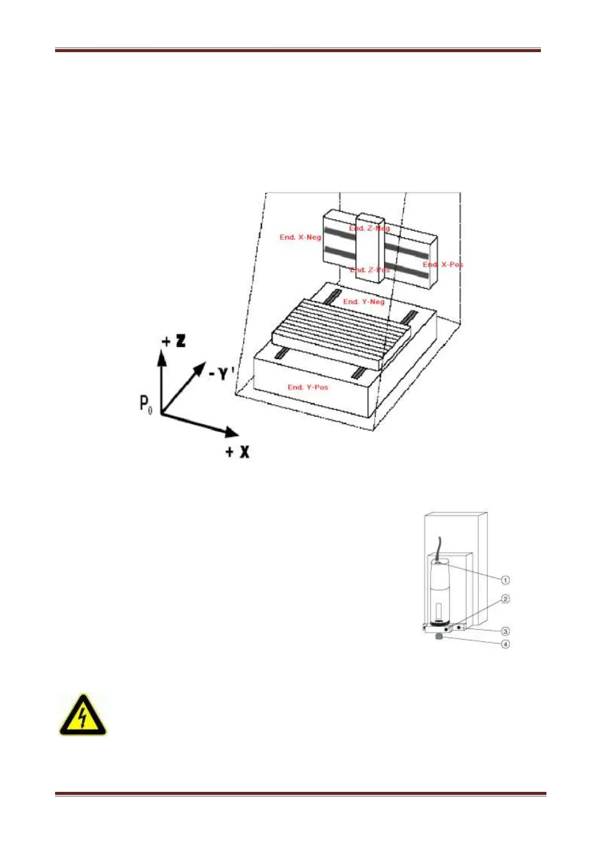
5.4 Coordinate system and reference point
The coordinate system of the machine is determined as shown in the figure. However, you
can select (displace) the P0 work piece zero point freely via software.
Ex works, the home position of the machine (machine origin) is defaulted to the back (Y), to
the left (X), and to the top (Z).
Labels on the machine mark the axes.
5.5 Tooling machine
In the collet (4) the standard tooling machine can take tools
with a maximum shaft diameter of 6.35 mm (standard 3 mm,
other diameters see Accessory). Use two SW 22 open end
wrenches for changing the collet.
The tooling machine is only enabled by the software. You can
manually adjust the rotation speed of the machine using the
(1)wheel.
Switch off the main switch of the ICP for dismantling the tooling
machine. Remove the electricity cable from the coupler terminal block,
loosen the clamping screw and take the tooling machine from the
holder.
For dismantling the machine with the holder, remove the electricity
cable, the two outside screws (3)
(loosen only, do not screw very out)
and remove the machine with holder and T-slot stones downwards.