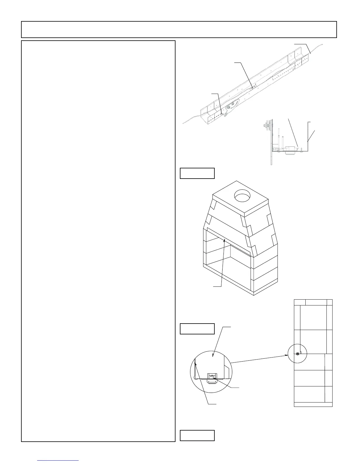
High Temperature
Limit Switch
2 High Temperature
Wires
Tab to be bent upward
to stand vertical
(both sides)
18
IBV Assembly Instructions (cont.)
Metal Canopy Installation:
The metal canopy, as supplied, is forty ve inches
(45”) long and ts the IBV models 36 & 46. Field cut the metal
canopy equally at the perforated lines as required for the 36”
unit. This will ensure the limit switch and micro-switch are
located in the proper position on the lintel.
Connect the two (2) leads from the high temperature
wires to the thermocouple junction block (see diagram, page
29).
Measure and locate the centerline of the replace
opening. Align notch at the front of the lintel to the centerline
of the replace. Install lintel using 1 1/2” masonry screws.
Notes: The limit switch and microswitch are already supplied
and mounted in the IBV metal canopy component. Connect the
two high temperature wires (coming out the top of the IBV left
hand rebox side wall) to the two high temperature wires that
are attached to the limit switch with ceramic wire nuts.
The small tab near damper lever should be bent
upward to stand vertical. This protects wires passing through
the harness.
WARNING: Do not bypass the high temperature limit switch.
Install downdraft diverter at the top plate. (Figure 20)
Orient assembly such that the wire cable is toward the
front of the replace opening.
Loosen screws on the cable clamp and loop between
the two washers at the end of the handle asembly.
Note: Wire clamp should be approximately 4” from the washers.
Tighten lock nuts on the handle if necessary.
Pull cable to close the damper and adjust the length
of wire cable by swinging the handle between open and close
positions. When in the open position, the damper should be
rotated a full 90 degrees from the closed position.
Retighten screws on the cable clamp and remove
excess cable.
The metal canopy ts horizontally up toward the
bottom of the smoke dome. The adjoining short leg of the
metal canopy ts up against the bottom of the smoke dome
component. (Figure 19)
The metal canopy has 4 pilot holes for the screw placement.
Attach the metal canopy ush against the front face of
the smoke dome with 4 mounting screws driven into the face of
the IBV smoke dome.
Any excess wire draped between the metal canopy and
the left hand rebox sidewall should be neatly tucked into the
hollow core of the left hand sidewall. Excess wire should not be
visible below the canopy bottom.
The 2 high temperature wires inside of the IBV rebox
will connect to the appropriate contacts found on the gas log
assembly during the installation of the gas log set.
Front
Facing
Limit Switch
Terminals
Smoke Dome
Component
Metal Canopy
High Temperature
Limit Switch
Metal Canopy
Figure 17
Figure 18
Figure 19
 Loading...