18-28
18. BF200D • BF225D • BF250D iST
®
RIGGING DIAGRAMS
MULTI-ENGINE NUMBERING
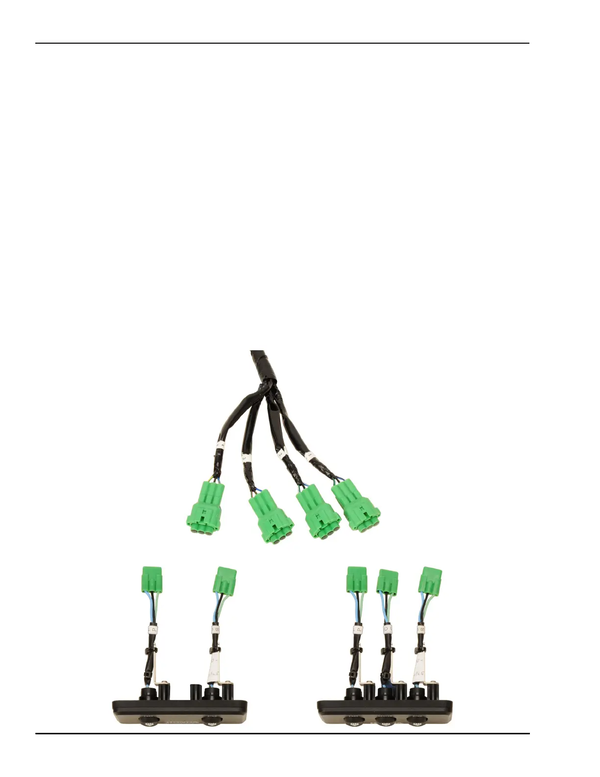
Push-Button Start and Power Trim/Tilt Panels
The connectors for the push-button start panel, power trim/tilt panel and main harness are labeled where
multi-engine configurations are available. Panel harnesses are labeled with letters and the Control ECU
harnesses are labeled with numbers. To correctly connect the panels to the correct engine, follow the
instructions below and the rigging diagrams on the following pages.
Twin-engine
Port (P) connects to engine 1 connector.
Starboard (S) connects to engine 2 connector.
Triple-engine
Port (P) connects to engine 1 connector.
Center (C) connects to engine 2 connector.
Starboard (S) connects to engine 3 connector.
Quad-engine
Port (P) on left panel connects to engine 1 connector.
Starboard (S) on left panel connects to engine 2 connector.
Port (P) on right panel connects to engine 3 connector.
Starboard (S) on right panel connects to engine 4 connector.