6A–50 ENGINE MECHANICAL
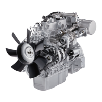
Valve Guide Installation
1. Apply engine oil to the valve guide outer
circumference.
2. Set the ring to the valve guide replacer 5-8840-2628-
0.
3. Attach the valve guide replacer with ring to the valve
guide.
4. Use a hammer to drive the valve guide into position
from the cylinder head upper face.
5. Measure the height of the valve guide upper end
from the upper face of the cylinder head.
Valve Guide Upper End Height (Reference): 14.1
mm (0.56 in)
NOTE: If the valve guide has been removed, both the
valve and the valve guide must be replaced as a set.
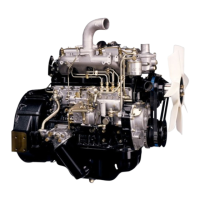
Valve and Valve Seat Insert
Valve Thickness
Measure the valve thickness.
If the measured value is less than the specified limit, the
valve and the valve guide must be replaced as a set.
Intake and Exhaust Valve Thickness
Intake Valve
Standard: 1.71 mm (0.067 in)
Limit: 1.30 mm (0.051 in)
Exhaust Valve
Standard: 1.75 mm (0.069 in)
Limit: 1.30 mm (0.051 in)
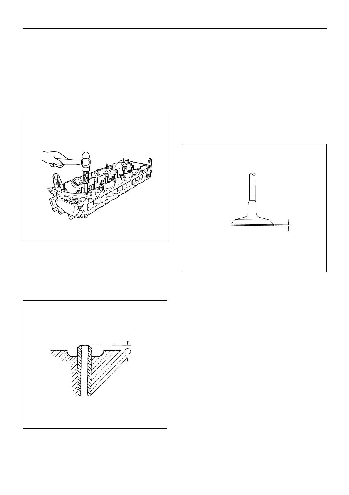
Valve Depression
1. Install the new valve (1) to the cylinder head (2).
2. Use a depth gauge or a straight edge with steel rule
to measure the valve depression from the cylinder
head lower surface.
If the measured value exceeds the specified limit, the
valve seat insert must be replaced.
Valve Depression
Intake Valve
Standard: 1.0 mm (0.039 in)
Limit: 2.5 mm (0.098 in)
Exhaust Valve
Standard: 1.3 mm (0.051 in)
Limit: 2.8 mm (0.110 in)
011MX024

 Loading...