ENGINE MECHANICAL 6A–11
Installation
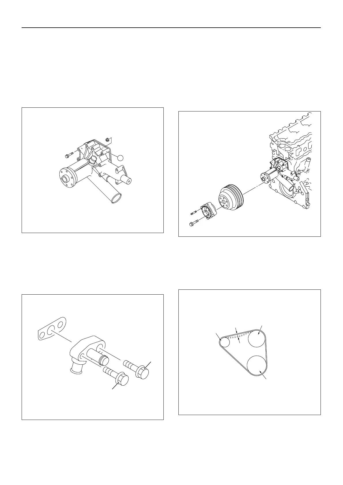
1. Install the water pump with new gaskets to the front
plate. Use the locating pin.
2. Tighten the fixing nuts and bolts to the specified
torque.
Torque:
Nut A: 39 N·m (4.0 kgm/29 lbft)
Bolt: 20 N·m (2.0 kgm/14 lbft)
3. Install the water duct with new gasket to the cylinder
head.
Tighten the bolts to the specified torque.
Torque:
Bolt (1) : 240 N·m (24 kgm/174 lbft)
Bolt (2) : 20 N·m (2.0 kgm/14 lbft)
4. Install the water duct with new gasket to the oil cooler
and water pump.
Tighten the bolts to the specified torque.
Torque: 20 N·m (2.0 kgm/14 lbft)
5. Connect the bypass hose.
6. Clamp the bypass hose.
7. Install the fan pulley and adaptor to the water pump.
Tighten the fixing bolts to the specified torque.
Torque: 52 N·m (5.3 kgm/38 lbft)
8. Install the fan belt.
9. Adjust the fan belt tension.
• Depress the drive belt midway between the
alternator and fan pulley.
Drive Belt Deflection: 8 - 11 mm (0.31 - 0.43 in)

 Loading...


