6A–34 ENGINE MECHANICAL
6. If the “B” mark and upper cylinder head face are
not aligned, No.1 piston is not on the compression
stroke.
Remove the camshaft.
Rotate the crankshaft one full turn and realign the
crankshaft damper pulley TDC mark with the
pointer by rotating the crankshaft in the normal
direction of engine rotation.
7. Reinstall the camshaft assembly repeating steps 3
to 5.
2. Install the camshaft bearing caps.
1. Apply engine oil to the camshaft bearing sliding
surfaces.
2. Install the camshaft bearing caps with the
bearings in numerical order with the cap stamped
mark facing forward.
3. Apply engine oil to the bearing cap bolt threads
and setting faces.
4. Tighten the bearing cap bolts to the specified
torque. Work from the center of the cylinder head
toward the outside.
Torque: 27 N·m (2.8 kgm/20 lbft)
3. Apply engine oil to the bridge cap.
4. Install the rocker arm assembly.
Refer to “Rocker Arm Assembly Installation” in this
manual.
5. Adjust the valve clearance.
Refer to “Valve Clearance Adjustment” in this
manual.
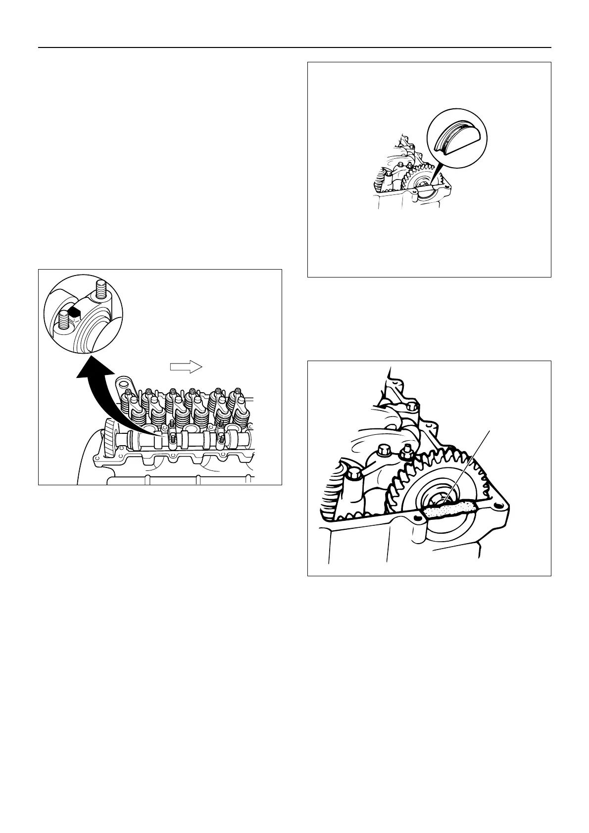
6. Install the rubber plug to the cylinder head.
1. Apply ThreeBond 1207B or equivalent to the
rubber plug as shown in the illustration.
2. Install the rubber plug to the cylinder head.
NOTE : Clean the cylinder head and remove sealant
residue.
3. Apply ThreeBond 1207B or equivalent to the
rubber plug surfaces.
NOTE : Immediately (within ten (10) minutes of applying
the sealant) install the cylinder head cover to the
cylinder head.
7. Install the cylinder head cover with new gasket.
1. Clean the head cover gasket groove and the head
cover gasket.
2. Install the new head cover gasket and collar to the
head cover.
3. Install the cylinder head cover to the cylinder
head.
011MV009-1
015EY00077

 Loading...


