Single Phase Voltage Regulator RAV-2
with control CTR-2
Instruction Manual MI-010
Page: 11/27
Rev. 06/2017
REGULATOR OPENING
To verify internally open regulator as indicated:
1. Remove regulator from service, follow security instructions indicated on control panel;
2. Place the regulator on a place where energized line cannot interfere. An indoor, flat leveled floor place is
preferred. Wait till isolation oil temperature is less than 40 degrees Celsius;
3. Remove bolts that fasten control cabinet box to tank;
Note: Do not disconnect control from regulator cover. Box has to be mechanically connected
to box during opening.
4. Remove earth conductor connected between control box and tank;
5. Remove bolts from cover fixation;
6. Remove earth conductor connected between cover and tank;
7. Lift active part by the lifting eye located on cover, guiding control box which will be lifted together with cover;
DANGER: when opening the regulator there will be human and ambiental contact with
isolating oil. Usage of adequate security equipment is
TAP CHANGER
Derivation on load tap changer is a simple device with long expected life time when recommended inspections as
indicated in table 3 are performed.
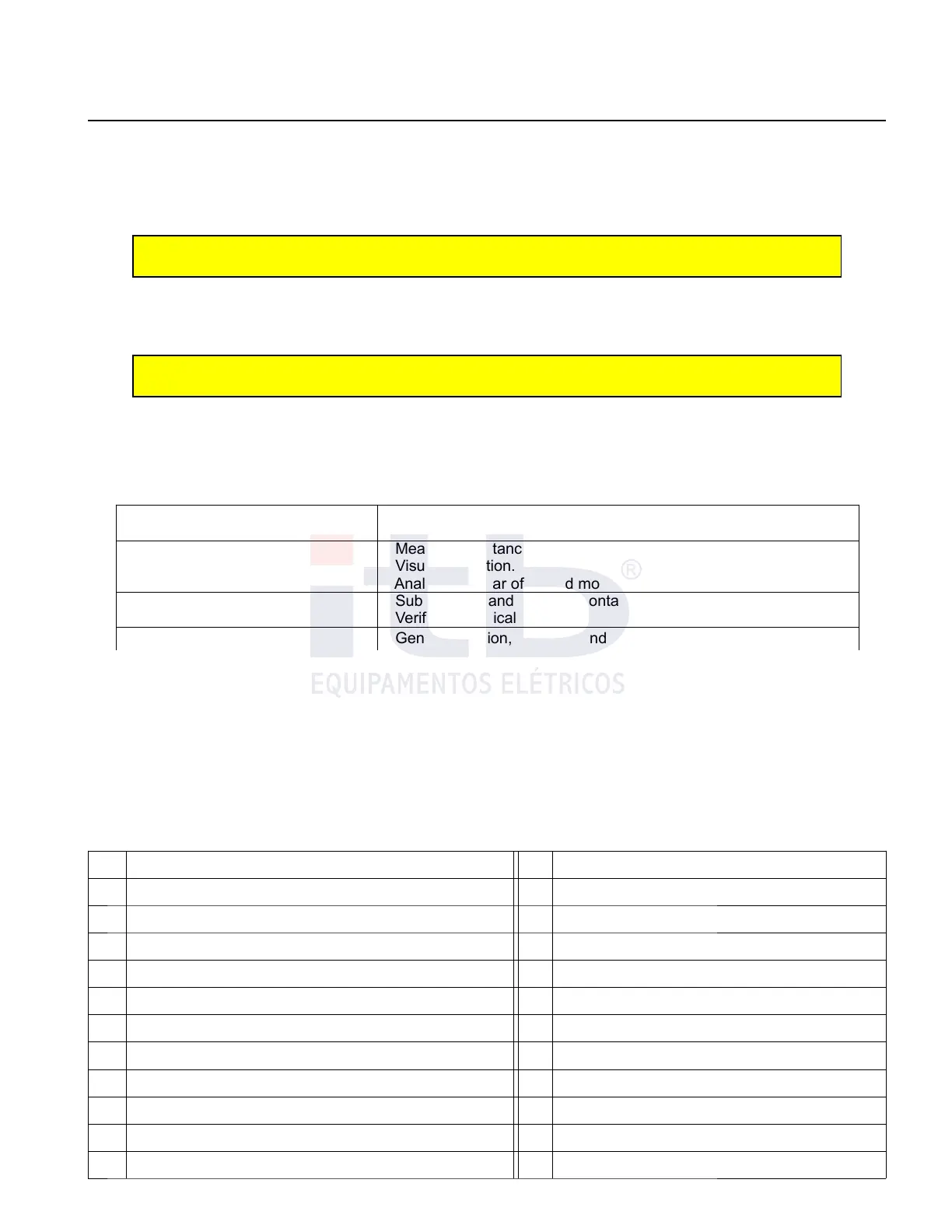
Table 3: On load tap changer inspections
FREQUENCY
Number of operations
SERVICES DESCRIPTION
Each 125,000
- Measure resistance contact (800μΩ max).
- Visual inspection.
- Analysis of wear of fix and movable contacts.
Each 250,000
- Substitute fix and movable contacts.
- Verify mechanical operation.
Each 1,000,000 - General revision, unmount and change wear parts
Measurement of contact resistance (fixed contact + movable contact + axles + slip ring) must be done by connecting
Microohmmeter terminals between terminals of axis and collector ring (central straps of insulating plate switch).
Perform measurements on pairs taps from 0 to +16. The measured values for new switches may not exceed 800
μΩ. The natural wear of contacts, misalignments and clearances of mechanisms gradually increase this resistance.
Consider the value of 2,500 μΩ as maximum acceptable limit for the tap changers in operation.
Reposition pieces
Reposition pieces of tap changer can be requested as per drawing in Figure 12 and can be requested by its number
or name indicated on Table 4.
Table 4: List of parts of the under load tap changer.
It. Description It. Description
01 Collector came 17 Fix contact
02 Absolute Encoder 18 Ring collector
03 Micro Switch of operation counter 19 Brush
04 Assembly plate 20 Screw conductor
05 Micro switch of polarity 21 Axis collector
06 Reverse gear trigger 22 Insulating arm of the main tiger
07 Mobile contacts tiger 23 Mechanical indicator - Crown
08 Insulating arm tiger of the reverse gear 24 Mechanism axis
09 Disk of inertia 25 Trigger / Positioned
10 Mobile contact arm to the axis 26 Spring trigger fixing
11 Mobile contact arm to the to the ring 27 Trigger disk
ITB - Equipamentos Elétricos Ltda.