Single Phase Voltage Regulator RAV-2
with control CTR-2
Instruction Manual MI-010
Page: 23/27
Rev. 06/2017
Firmware
Name Action
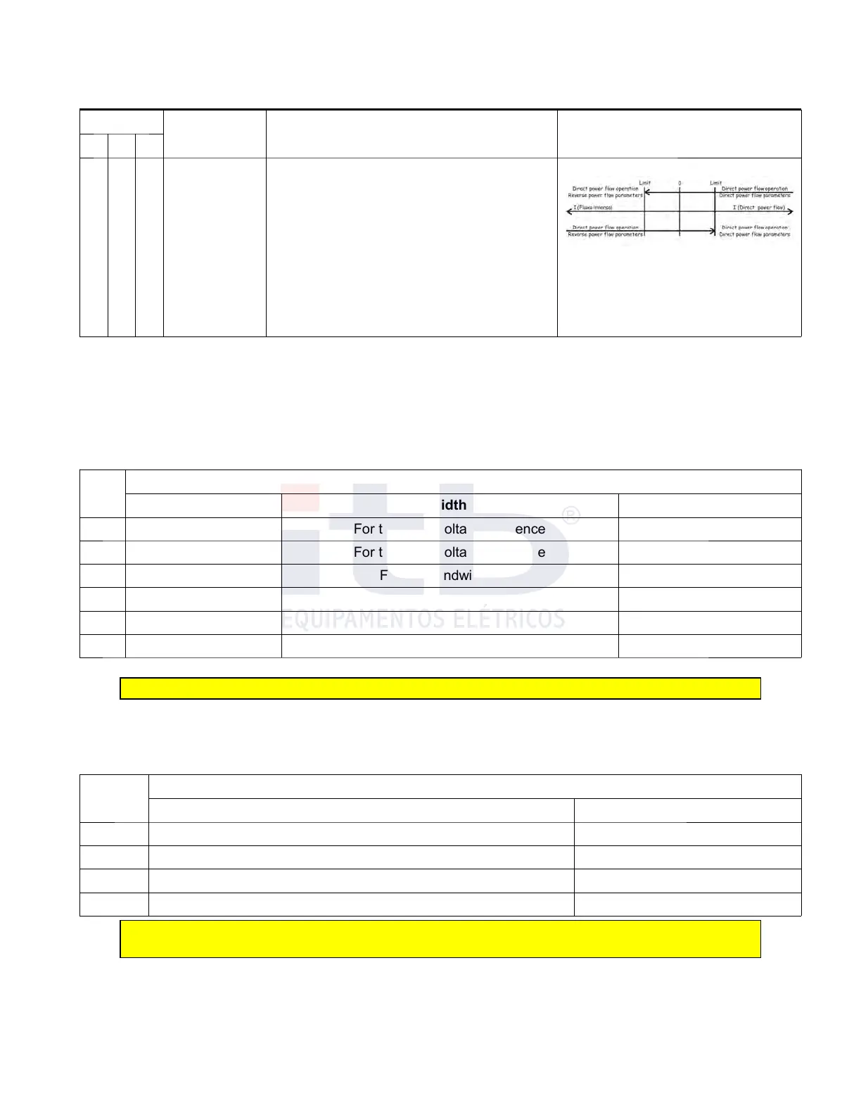
Functional Diagram
>2.5 =2.5 <2.5
8 4 4 Co-generation
Regulates only load side on both flow senses and
consideres all inverse power flow is due to co-
generation. This is to be used when direct and inverse
power flow can happen and inverse power flow is
caused by a distributed generation set of Little size.
CTR-2, when a current in inverse flow is detected
bigger than percentage value of nominal current set in
parameter 49 Lock Limit (LIMBL) works on inverse flow
until current is once again equal to or biggher than
same value but on direct power flow where it operates
on direct power flow.
44 - Tap changer actuation, insensibility treatment and extreme locks.
To allow controls CTR-2 of or single phase voltage regulator operate with regulators made by other manufacturers,
it is necessary to configure the way the motor needs to work if, continuous or pulse, and whether there are or not
switches locking extreme positions. In addition,user can select if CTR-2 will, once motor is activated, change tap
until tension exceeds reference tension or if it will change until sensibility limit is achieved.
Adjustments can be made according to table 12.
Table 12: Tap changer working method, insensibility treatment and extreme locking
Valor
Way of actuation and block
Motor Actuation Bandwidth Tract Extremes blocking
0 Continuous For the rated voltage reference Without switch
1 Pulsed For the rated voltage reference Without switch
2 Continuous For the bandwidth rate Without switch
3 Pulsed For the bandwidth rate Without switch
4 Continuous For the rated voltage With switch
5 Continuous For the bandwidth rate With switch
Note: For ITB regulators this parameters need to be set in values “0” or “2”.
45 - Tap changer position Reading method
CTR-2 control has two ways to obtain actual tap changer position that can be choosed by programming this
parameter as per table 13.
Table 13: tap changer position Reading methods
Value
Method for checking the position of the tap changer
Reading Method Remote Indication
0 Absolute BDC encoder real time reading -16 to +16
1 Absolute BDC encoder real time reading 01 to 33
2 By tracking -16 to +16
3 By tracking 01 to 33
Note: Options 2 and 3 must be used when absolute encoder cannot be used. It is not 100%
secure and thus not reliable for load bonus and máximum/mínimum lock positions
46 - Phase shift between voltage and current
For a regulator to operate properly current dependent operations such as line voltage drop compensation, and
display the correct values of power factor CTR-2 is necessary to be adjusted so as to consider the the phase shift
between current and voltage that changes depending on the mounting connection. This parameter is set on the
control by setting its "DEFVC" function, which can take the "0" (zero) values if there is no lag between voltage and
ITB - Equipamentos Elétricos Ltda.