Single Phase Voltage Regulator RAV-2
with control CTR-2
Instruction Manual MI-010
Page: 16/27
Rev. 06/2017
- Key 16, “Raise” key operates the tap changer in the sense of increasing the tap changer position when manual
mode is active. Manual mode is identified by “man” in the last field of the third line of the standard screen;
- Key 17, “Auto” key selects operation mode from automatic to manual.
Auto Zero
The key 14, key, “Auto zero”, is programmed to take the regulator to a secure operation condition for energization
and de-energization and once pressed the following actions are done:
a - Verify actual tap changer position;
b - If position is not nominal position, verify if on load tap changer needs to boost or buck;
c - Connect tap changer motor in correct sense so as to take tap changer to nominal position;
d - Wait until zero position is achieved;
e - When zero position is achieved verify redundancy in information comparing encoder Reading with micro
switch closed at nominal position which have electrical and mechanical independence;
f - Lit the “Bypass” led if redundancy presents incoherence between nominal position led and encoder;
g -Lights the led “Neutral” in case the redundancy confirms the nominal position.
h - Show in screen “tap changer in neutral position ready for operation”;
i - Lit the “Fail” led if there is difference in redundancy between nominal position led and encoder reading;
j - Show in screen “tap changer blocked. Auto zero fault” in case there is difference in redundancy between
nominal position led and encoder reading.
Note: “Auto zero” blocks control keys until next energization and always returns to normal
mode
Navigation in reading screens
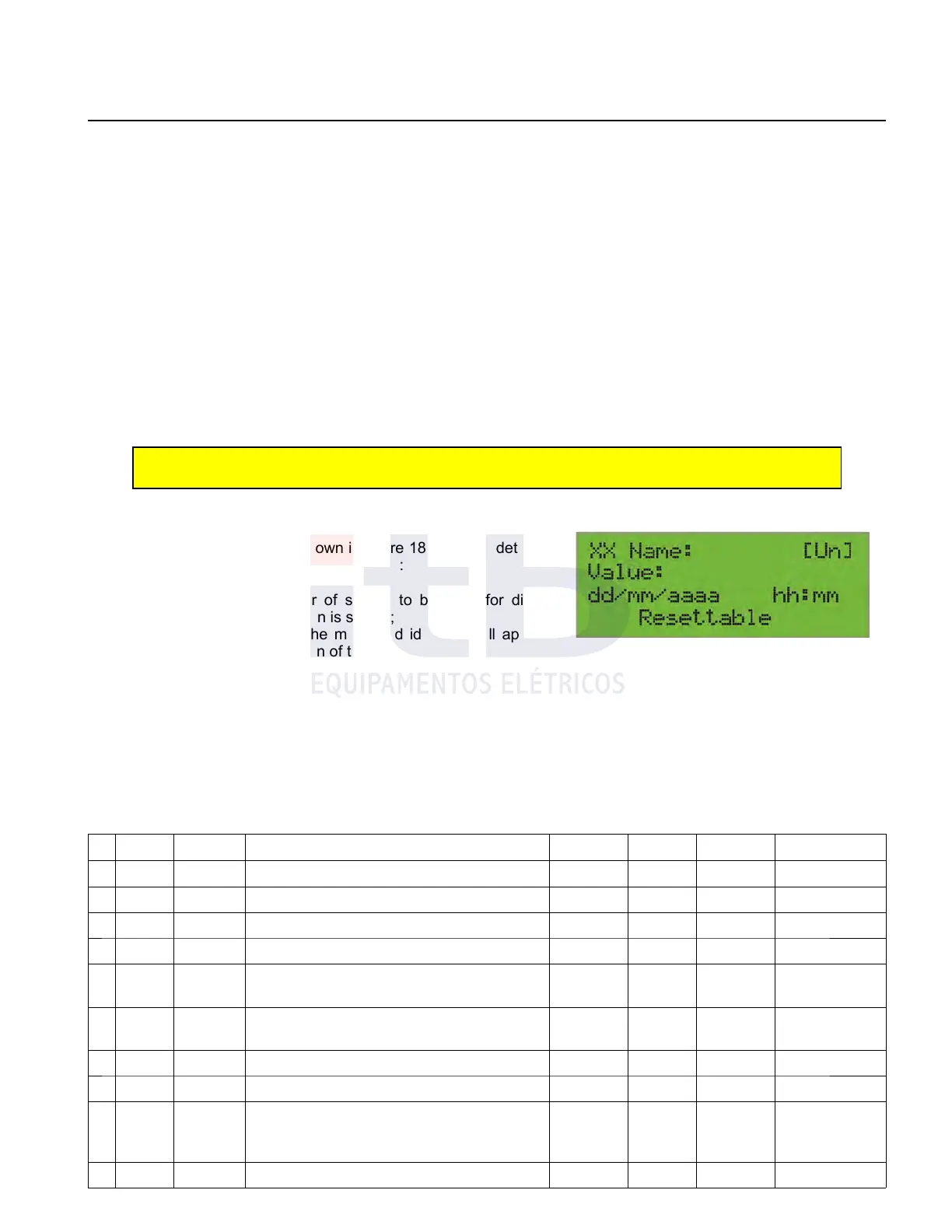
From the standard screen by pressing the “+” or “-“ key user can
navigate between screens, as shown in figure 18, in which detailed
system measured values are shown as follow:
1. In the “XX” field the number of screen to be used for direct
access through shortcut screen is shown;
2. In the “Nome” field (name) the measured identifier will appear
as described in “Name” column of table 6;
3. In field between brackets the unit of value (when appropriate)
will be displayed;
4. In the “Value” field the instantaneous value for that measurement will be displayed;
5. In the “dd/mm/aaaa hh:mm” field the occurrence moment will be displayed if appropriate;
6. The Word “Resettable” (able to reset) will be displayed on the last row of the screen if variable can be reseted as
described in table 6.
Values will be shown in Table 6 sequence to drive straight away using the "+" key and the "-"
Table 6: Sequence of measured values.
S.
Shortcut
Name Description Date Time Unit
Resettable
Remote
01 66
TBLC
Low tension voltage on "Load" - V - display
02 67
TBLF
Low tension voltage on “Source” - V - display
03 68
FREQ
Frequency - Hz - display
04 69
FPOT
Power factor - - - display
05 70
DMAXTC
Maximum voltage demand on "Load" Yes V Yes
display and
resets
06 71
DMINTC
Minimum voltage demand on "Load" Yes V Yes
display and
resets
07 72
TLC
Line voltage on "Load" - kV - display
08 73
CLC
Line current on "Load" - A - display
09 74
DMAXCC
Maximum current demand on "Load" Yes mA Yes
display and
resets
10 75
DMINCC
Minimum current demand on "Load" Yes mA Yes display and
ITB - Equipamentos Elétricos Ltda.
Figure 18: Measurement reading screen.